DTCs explained
#1
This is a thread for explainations of common DTCs. Just scroll down to find certain DTCs.
[hr]
P0154 - HO2S Circuit Insufficient Activity Bank 2 Sensor 1
Schematic
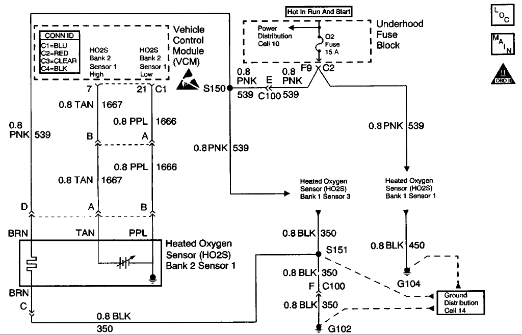
CIRCUIT DESCRIPTION
The Heated Oxygen sensor (HO2S) is a sensor designed to create a voltage relative to the oxygen content in the engine exhaust stream. The control module supplies the HO2S with signal high and low circuits. Ignition voltage and ground are supplied to the HO2S heater by independent circuits. The oxygen content of the exhaust indicates when the engine is operating lean or rich. When the HO2S detects that the engine is operating rich, the signal voltage is high, and decreases the signal voltage as the engine runs leaner. This oscillation above and below the bias voltage, sometimes referred to as activity or switching, can be monitored with the HO2S signal voltage.
The HO2S contains a heater that is necessary in order to quickly warm the sensor to operating temperature. The heater also maintains the operating temperature during extended idle conditions. The HO2S needs to be at a high temperature in order to produce a voltage. When the HO2S reaches operating temperature, the control module monitors the HO2S bias, or reference, voltage. It also monitors the HO2S signal voltage for Closed Loop fuel control. During normal Closed Loop fuel control operation, the control module will add fuel, or enrich the mixture, when the HO2S detects a lean exhaust content. The control module will subtract fuel, or "lean-out" the mixture, when the HO2S detects a rich exhaust condition.
Certain vehicle models utilize an oxygen sensor behind the catalytic converter in order to monitor catalyst efficiency.
This Diagnostic Trouble Code (DTC) determines if the HO2S is functioning properly. It checks for an adequate number of HO2S voltage transitions above and below the bias range of 300-600 mV . This DTC sets when the Vehicle Control Module (VCM) fails to detect a minimum number of voltage transitions above and below the bias range during the test period. Possible causes of this DTC are:
* An open or a short to voltage on either the HO2S signal or HO2S low circuits
* A malfunctioning HO2S
* A problem in the HO2S heater or its circuit
* A faulty HO2S ground
This DTC determines if the HO2S is functioning properly by checking for an adequate number of HO2S voltage transitions above and below the bias range of 300-600 mV . This DTC sets when the VCM fails to detect a minimum number of voltage transitions above and below the bias range during the test period. Possible causes of this DTC are listed below.
* An open circuit or a short to voltage on either the HO2S signal or HO2S low circuits
* A malfunctioning HO2S
* A problem in the HO2S heater or its circuit
* A poor HO2S ground
CONDITIONS FOR RUNNING THE DTC
* No active TP sensor DTCs
* No active EVAP system DTCs
* No active IAT sensor DTCs
* No active MAP sensor DTCs
* No active ECT sensor DTCs
* No active MAF sensor DTCs
* No active misfire DTCs
* No intrusive test in progress
* No device controls acti
[hr]
P0154 - HO2S Circuit Insufficient Activity Bank 2 Sensor 1
Schematic

CIRCUIT DESCRIPTION
The Heated Oxygen sensor (HO2S) is a sensor designed to create a voltage relative to the oxygen content in the engine exhaust stream. The control module supplies the HO2S with signal high and low circuits. Ignition voltage and ground are supplied to the HO2S heater by independent circuits. The oxygen content of the exhaust indicates when the engine is operating lean or rich. When the HO2S detects that the engine is operating rich, the signal voltage is high, and decreases the signal voltage as the engine runs leaner. This oscillation above and below the bias voltage, sometimes referred to as activity or switching, can be monitored with the HO2S signal voltage.
The HO2S contains a heater that is necessary in order to quickly warm the sensor to operating temperature. The heater also maintains the operating temperature during extended idle conditions. The HO2S needs to be at a high temperature in order to produce a voltage. When the HO2S reaches operating temperature, the control module monitors the HO2S bias, or reference, voltage. It also monitors the HO2S signal voltage for Closed Loop fuel control. During normal Closed Loop fuel control operation, the control module will add fuel, or enrich the mixture, when the HO2S detects a lean exhaust content. The control module will subtract fuel, or "lean-out" the mixture, when the HO2S detects a rich exhaust condition.
Certain vehicle models utilize an oxygen sensor behind the catalytic converter in order to monitor catalyst efficiency.
This Diagnostic Trouble Code (DTC) determines if the HO2S is functioning properly. It checks for an adequate number of HO2S voltage transitions above and below the bias range of 300-600 mV . This DTC sets when the Vehicle Control Module (VCM) fails to detect a minimum number of voltage transitions above and below the bias range during the test period. Possible causes of this DTC are:
* An open or a short to voltage on either the HO2S signal or HO2S low circuits
* A malfunctioning HO2S
* A problem in the HO2S heater or its circuit
* A faulty HO2S ground
This DTC determines if the HO2S is functioning properly by checking for an adequate number of HO2S voltage transitions above and below the bias range of 300-600 mV . This DTC sets when the VCM fails to detect a minimum number of voltage transitions above and below the bias range during the test period. Possible causes of this DTC are listed below.
* An open circuit or a short to voltage on either the HO2S signal or HO2S low circuits
* A malfunctioning HO2S
* A problem in the HO2S heater or its circuit
* A poor HO2S ground
CONDITIONS FOR RUNNING THE DTC
* No active TP sensor DTCs
* No active EVAP system DTCs
* No active IAT sensor DTCs
* No active MAP sensor DTCs
* No active ECT sensor DTCs
* No active MAF sensor DTCs
* No active misfire DTCs
* No intrusive test in progress
* No device controls acti
#2
P0740 - Torque Converter Clutch Circuit
Schematic
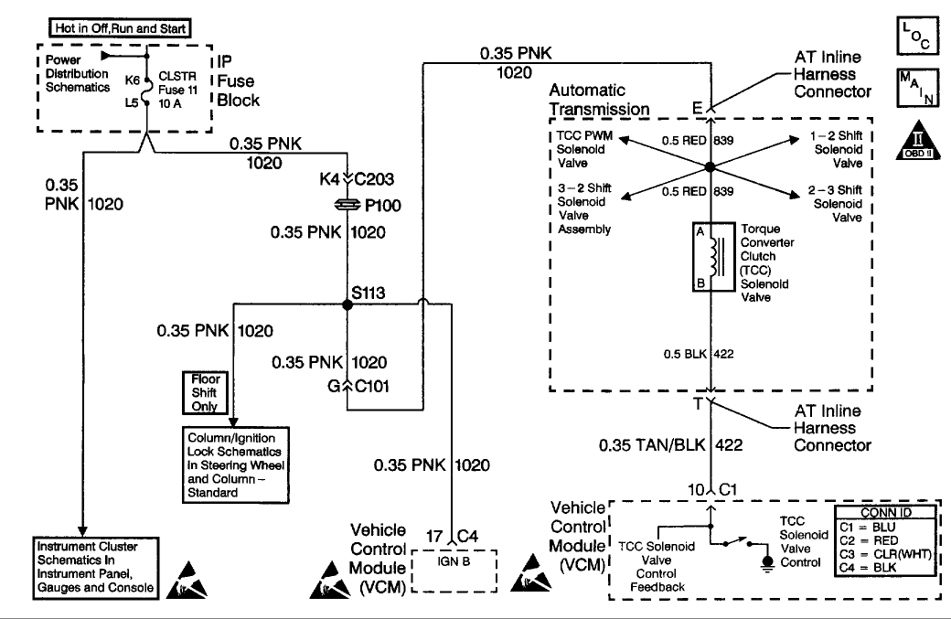
CIRCUIT DESCRIPTION
The Torque Converter Clutch (TCC) solenoid valve is an electrical device that is used with the Torque Converter Clutch Pulse Width Modulation (TCC PWM) solenoid valve in order to control TCC apply and release. The TCC solenoid valve attaches to the transmission case assembly extending into the pump cover. The TCC solenoid valve receives ignition voltage through circuit 1020. The Vehicle Control Module (VCM) controls the solenoid by providing the ground path on circuit 422. The VCM monitors the Throttle Position (TP) voltage, the vehicle speed, and other inputs in order to determine when to energize the TCC solenoid valve.
When the VCM detects a continuous open, short to ground, or short to power in the TCC solenoid valve circuit, then DTC P0740 sets. DTC P0740 is a type A DTC.
CONDITIONS FOR RUNNING THE DTC
* The system voltage is 10-19 volts .
* The engine speed is greater than 450 RPM for 5 seconds .
* The engine is not in fuel cutoff.
CONDITIONS FOR SETTING THE DTC
DTC P0740 sets if one of the following conditions occurs for 5 seconds :
Condition 1
The VCM commands the solenoid ON and the voltage feedback remains high (B+).
Condition 2
The VCM commands the solenoid OFF and the voltage feedback remains low (0 volt ).
ACTION TAKEN WHEN THE DTC SETS
* The VCM illuminates the Malfunction Indicator Lamp (MIL) .
* The VCM inhibits TCC engagement.
* The VCM inhibits 4th gear if the transmission is in hot mode.
* The VCM freezes shift adapts from being updated.
* The VCM records the operating conditions when the Conditions for Setting the DTC are met. The VCM stores this information as Freeze Frame and Failure Records.
* The VCM stores DTC P0740 in VCM history.
CONDITIONS FOR CLEARING THE MIL/DTC
* The VCM turns OFF the MIL during the third consecutive trip in which the diagnostic test runs and passes.
* A scan tool can clear the MIL/DTC.
* The VCM clears the DTC from VCM history if the vehicle completes 40 warm-up cycles without an emission-related diagnostic fault occurring.
* The VCM cancels the DTC default actions when the fault no longer exists and/or the ignition switch is OFF long enough in order to power down the VCM.
DIAGNOSTIC AIDS
* Inspect the connector at the VCM and all other circuit connecting points for an intermittent condition. Refer to Testing for Intermittent and Poor Connections in Diagrams.
* Inspect the circuit wiring for an intermittent condition. Refer to Testing for Electrical Intermittents in Diagrams.
* With the TCC engaged, the TCC slip speed should be -20 to +50 RPM .
* A faulty ignition switch may set this code.
Diagnostic Chart (Part 1 Of 3)
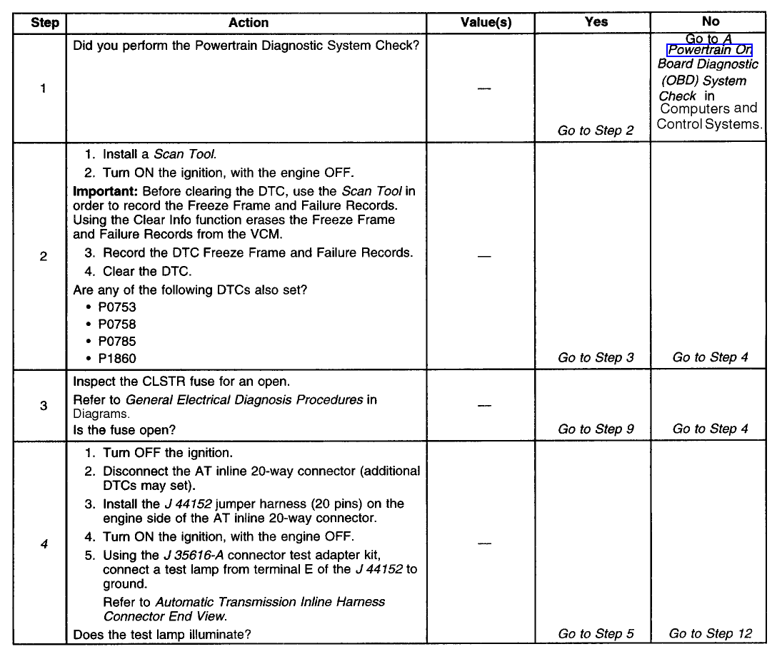
Diagnostic Chart (Part 2 Of 3)
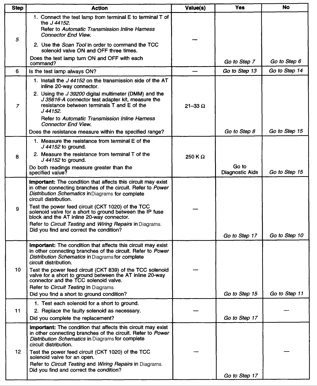
Diagnostic Chart (Part 3 Of 3)
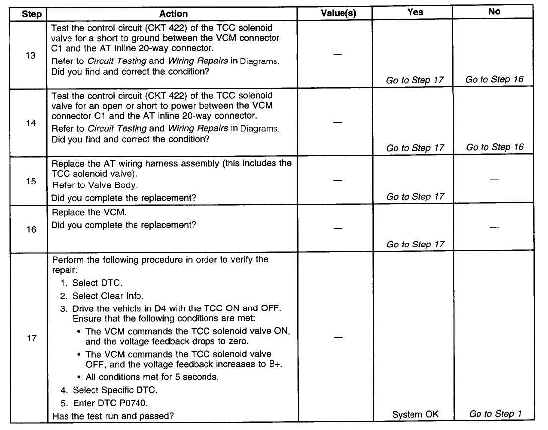
TEST DESCRIPTION
The numbers below refer to the step numbers on the diagnostic table.
4. This step tests for voltage to the solenoid.
5. This step tests the ability of the VCM and wiring to control the ground circuit.
7. This step te
Schematic

CIRCUIT DESCRIPTION
The Torque Converter Clutch (TCC) solenoid valve is an electrical device that is used with the Torque Converter Clutch Pulse Width Modulation (TCC PWM) solenoid valve in order to control TCC apply and release. The TCC solenoid valve attaches to the transmission case assembly extending into the pump cover. The TCC solenoid valve receives ignition voltage through circuit 1020. The Vehicle Control Module (VCM) controls the solenoid by providing the ground path on circuit 422. The VCM monitors the Throttle Position (TP) voltage, the vehicle speed, and other inputs in order to determine when to energize the TCC solenoid valve.
When the VCM detects a continuous open, short to ground, or short to power in the TCC solenoid valve circuit, then DTC P0740 sets. DTC P0740 is a type A DTC.
CONDITIONS FOR RUNNING THE DTC
* The system voltage is 10-19 volts .
* The engine speed is greater than 450 RPM for 5 seconds .
* The engine is not in fuel cutoff.
CONDITIONS FOR SETTING THE DTC
DTC P0740 sets if one of the following conditions occurs for 5 seconds :
Condition 1
The VCM commands the solenoid ON and the voltage feedback remains high (B+).
Condition 2
The VCM commands the solenoid OFF and the voltage feedback remains low (0 volt ).
ACTION TAKEN WHEN THE DTC SETS
* The VCM illuminates the Malfunction Indicator Lamp (MIL) .
* The VCM inhibits TCC engagement.
* The VCM inhibits 4th gear if the transmission is in hot mode.
* The VCM freezes shift adapts from being updated.
* The VCM records the operating conditions when the Conditions for Setting the DTC are met. The VCM stores this information as Freeze Frame and Failure Records.
* The VCM stores DTC P0740 in VCM history.
CONDITIONS FOR CLEARING THE MIL/DTC
* The VCM turns OFF the MIL during the third consecutive trip in which the diagnostic test runs and passes.
* A scan tool can clear the MIL/DTC.
* The VCM clears the DTC from VCM history if the vehicle completes 40 warm-up cycles without an emission-related diagnostic fault occurring.
* The VCM cancels the DTC default actions when the fault no longer exists and/or the ignition switch is OFF long enough in order to power down the VCM.
DIAGNOSTIC AIDS
* Inspect the connector at the VCM and all other circuit connecting points for an intermittent condition. Refer to Testing for Intermittent and Poor Connections in Diagrams.
* Inspect the circuit wiring for an intermittent condition. Refer to Testing for Electrical Intermittents in Diagrams.
* With the TCC engaged, the TCC slip speed should be -20 to +50 RPM .
* A faulty ignition switch may set this code.
Diagnostic Chart (Part 1 Of 3)

Diagnostic Chart (Part 2 Of 3)

Diagnostic Chart (Part 3 Of 3)

TEST DESCRIPTION
The numbers below refer to the step numbers on the diagnostic table.
4. This step tests for voltage to the solenoid.
5. This step tests the ability of the VCM and wiring to control the ground circuit.
7. This step te
#3
P0420 - Catalyst System Efficiency Below Threshold (Bank 1)
Schematic
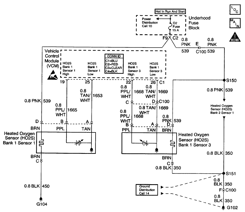
CIRCUIT DESCRIPTION
This diagnostic test is designed in order to measure the efficiency of the Three-way Catalytic Converter (TWC) system. Catalytic convertor efficiency is a measure of its ability to store oxygen after converting the levels of Hydrocarbon (HC) , Carbon Monoxide (CO) , and Oxides Of Nitrogen (NOx) to less harmful gases. The control module is able to evaluate the catalyst efficiency once the vehicle has met the enable criteria and the vehicle is at idle instead of the steady cruise speeds used in the past. Once the conditions for running this Diagnostic Trouble Code (DTC) are met, the control module commands either a lean or rich air/fuel ratio depending on the current state of the exhaust oxygen level. The control module issues a rich command if the exhaust is currently lean, or a lean command if the exhaust is currently rich. After completion of the first command, a second and opposite command is issued.
For example, if the control module were to command a rich mixture, the upstream Heated Oxygen Sensor (HO2S) voltage would increase immediately. The rich mixture is delayed in reaching the downstream HO2S due to the conversion process occurring within the converter. The higher the efficiency, the more the delay before the rich or lean mixture is detected by the downstream Oxygen (O2) sensor. As a result of the lower conversion efficiency within a damaged or poisoned catalyst, the delay in the rich or lean mixture reaching the downstream O2 sensor is significantly shorter. This DTC monitors the amount of time required for both the upstream and downstream HO2S voltages to cross a calibrated voltage threshold in response to the rich or lean command.
CONDITIONS FOR RUNNING THE DTC
* No active secondary AIR DTCs
* No active CMP sensor DTCs
* No active ECT sensor DTCs
* No active EGR DTCs
* No active Fuel Trim DTCs
* No active IAC DTCs
* No active IAT sensor DTCs
* No active MAF sensor DTCs
* No active MAP sensor DTCs
* No active O2 sensor DTCs
* No active transmission DTCs
* No active EVAP system DTCs
* No active TP sensor DTCs
* No active VS sensor DTCs
* No active misfire DTCs
* The engine speed is 900 RPM or more for more than 35 seconds since the last idle period.
* The engine has been running for more than 346 seconds and the long term fuel trim is stable.
* The predicted catalyst temperature is more than 475°C (887°F) .
* The system is in Closed Loop.
* The BARO is 73 kPa or more.
* The IAT is between -7 to 117°C (20-167°F) .
* The ECT is between 75-117°C (167-243°F) .
* The engine has been idling for less than 60 seconds .
* The actual engine speed is within 100 RPM of the desired idle speed.
CONDITIONS FOR SETTING THE DTC
The VCM determined that the oxygen storage capacity of the catalyst has degraded below a calibrated threshold.
ACTION TAKEN WHEN THE DTC SETS
* The control module illuminates the Malfunction Indicator Lamp (MIL) if a failure is detected during 2 consecutive key cycles.
* The control module sets the DTC and records the operating conditions at the time the diagnostic failed. The failure information is stored in the scan tool Freeze Frame and Failure Records.
CONDITIONS FOR CLEARING THE MIL OR DTC
* The control module turns OFF the MIL after 3 consecutive drive trips when the test has run and passed.
* A history DTC will clear if no fault condition
Schematic

CIRCUIT DESCRIPTION
This diagnostic test is designed in order to measure the efficiency of the Three-way Catalytic Converter (TWC) system. Catalytic convertor efficiency is a measure of its ability to store oxygen after converting the levels of Hydrocarbon (HC) , Carbon Monoxide (CO) , and Oxides Of Nitrogen (NOx) to less harmful gases. The control module is able to evaluate the catalyst efficiency once the vehicle has met the enable criteria and the vehicle is at idle instead of the steady cruise speeds used in the past. Once the conditions for running this Diagnostic Trouble Code (DTC) are met, the control module commands either a lean or rich air/fuel ratio depending on the current state of the exhaust oxygen level. The control module issues a rich command if the exhaust is currently lean, or a lean command if the exhaust is currently rich. After completion of the first command, a second and opposite command is issued.
For example, if the control module were to command a rich mixture, the upstream Heated Oxygen Sensor (HO2S) voltage would increase immediately. The rich mixture is delayed in reaching the downstream HO2S due to the conversion process occurring within the converter. The higher the efficiency, the more the delay before the rich or lean mixture is detected by the downstream Oxygen (O2) sensor. As a result of the lower conversion efficiency within a damaged or poisoned catalyst, the delay in the rich or lean mixture reaching the downstream O2 sensor is significantly shorter. This DTC monitors the amount of time required for both the upstream and downstream HO2S voltages to cross a calibrated voltage threshold in response to the rich or lean command.
CONDITIONS FOR RUNNING THE DTC
* No active secondary AIR DTCs
* No active CMP sensor DTCs
* No active ECT sensor DTCs
* No active EGR DTCs
* No active Fuel Trim DTCs
* No active IAC DTCs
* No active IAT sensor DTCs
* No active MAF sensor DTCs
* No active MAP sensor DTCs
* No active O2 sensor DTCs
* No active transmission DTCs
* No active EVAP system DTCs
* No active TP sensor DTCs
* No active VS sensor DTCs
* No active misfire DTCs
* The engine speed is 900 RPM or more for more than 35 seconds since the last idle period.
* The engine has been running for more than 346 seconds and the long term fuel trim is stable.
* The predicted catalyst temperature is more than 475°C (887°F) .
* The system is in Closed Loop.
* The BARO is 73 kPa or more.
* The IAT is between -7 to 117°C (20-167°F) .
* The ECT is between 75-117°C (167-243°F) .
* The engine has been idling for less than 60 seconds .
* The actual engine speed is within 100 RPM of the desired idle speed.
CONDITIONS FOR SETTING THE DTC
The VCM determined that the oxygen storage capacity of the catalyst has degraded below a calibrated threshold.
ACTION TAKEN WHEN THE DTC SETS
* The control module illuminates the Malfunction Indicator Lamp (MIL) if a failure is detected during 2 consecutive key cycles.
* The control module sets the DTC and records the operating conditions at the time the diagnostic failed. The failure information is stored in the scan tool Freeze Frame and Failure Records.
CONDITIONS FOR CLEARING THE MIL OR DTC
* The control module turns OFF the MIL after 3 consecutive drive trips when the test has run and passed.
* A history DTC will clear if no fault condition
#4
P0410 - Secondary Air Injection System
Schematic
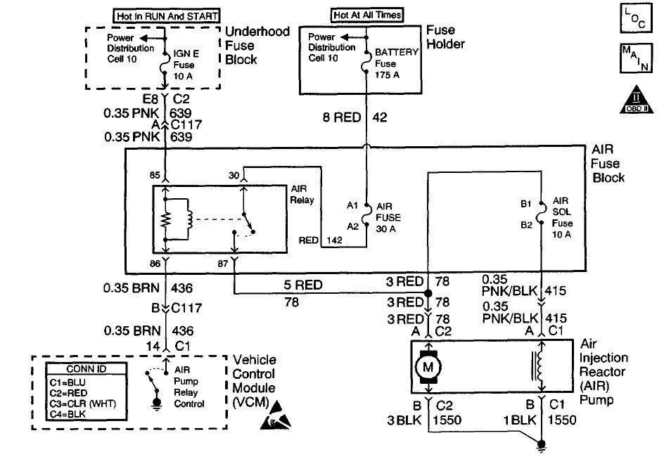
CIRCUIT DESCRIPTION
An AIR pump is used on this vehicle to lower tail pipe emissions at start-up. The Vehicle Control Module (VCM) supplies a ground to the AIR pump relay, which energizes the AIR pump and the AIR solenoid.
When the AIR pump is enabled, the VCM monitors the HO2S voltage. If the HO2S voltages go below a calibrated threshold value, the VCM interprets this as an indication that the AIR system is operational.
When the AIR pump is disabled, the VCM monitors the HO2S voltages. The HO2S voltages should increase above a calibrated threshold value and switch normally.
If the VCM did not sense more than a predetermined amount of HO2S rich switches, a malfunction will be reported.
The VCM will activate the AIR pump during Closed Loop operation. When the AIR system is activated, the VCM will monitor the HO2S voltages and Short Term Fuel Trim values for both banks of the engine. If the AIR system is operating properly, the HO2S voltages should go low and the short term fuel trim should go high.
The VCM checks that the HO2S voltages return to above a rich threshold when the AIR pump is disabled. If the VCM determines that the HO2S voltages for both banks did not respond as expected during the tests, DTC P0410 will set. If only one sensor responded, the VCM will set either a DTC P1415 or P1416 to indicate on which bank the AIR system is inoperative.
CONDITIONS FOR RUNNING THE DTC
* No active ECT sensor DTCs
* No active IAC sensor DTCs
* No active HO2S DTCs
* No active misfire DTCs
* No active MAP DTCs
* No active Fuel Trim DTCs
* No active EVAP DTCs
* No active TP sensor DTCs
* No active IAT DTCs
* No active MAF DTCs
* The MAF is less than 25 g/s .
* The commanded air/fuel ratio is 14.7:1.
* The engine load is less than 34 percent .
* Power Enrichment Mode is not active.
* DFCO (Decel Fuel Cutoff Mode) is not active.
* Catalyst overtemp protection is not active.
* The system has been in Closed Loop Mode for more than 20 seconds .
* The Short Term Fuel Trim is between 124-132 counts.
* The engine speed is more than 550 RPM .
* The ECT is between 80-110°C (176-230°F) .
* The system voltage is 11.7 volts or more.
CONDITIONS FOR SETTING THE DTC
* The O2 sensor voltage is less than 222 mV for more than 1.3 seconds , or
* The Short Term Fuel Trim value changes more than 20 percent when the secondary air injection pump is turned on and the system is in Closed Loop operation.
ACTION TAKEN WHEN THE DTC SETS
* The VCM illuminates the MIL during the second consecutive drive cycle in which the diagnostic reports a fail.
* The VCM will set the DTC and records the operating conditions at the time the diagnostic fails. The VCM stores the failure information in the scan tools Freeze Frame and Failure Records.
CONDITIONS FOR CLEARING THE MIL OR DTC
* The control module turns OFF the MIL after 3 consecutive drive trips when the test has run and passed.
* A history DTC will clear if no fault conditions have been detected for 40 warm-up cycles. A warm-up cycle occurs when the coolant temperature has risen 22°C (40°F) from the startup coolant temperature and the engine coolant reaches a temperature that is more than 70°C (158°F) during the same ignition cycle.
* Use a scan tool in order to clear the DTCs.
DIAGNOSTIC AIDS
Low AIR system volume may cause a DTC P1415, P1416 or an intermitt
Schematic

CIRCUIT DESCRIPTION
An AIR pump is used on this vehicle to lower tail pipe emissions at start-up. The Vehicle Control Module (VCM) supplies a ground to the AIR pump relay, which energizes the AIR pump and the AIR solenoid.
When the AIR pump is enabled, the VCM monitors the HO2S voltage. If the HO2S voltages go below a calibrated threshold value, the VCM interprets this as an indication that the AIR system is operational.
When the AIR pump is disabled, the VCM monitors the HO2S voltages. The HO2S voltages should increase above a calibrated threshold value and switch normally.
If the VCM did not sense more than a predetermined amount of HO2S rich switches, a malfunction will be reported.
The VCM will activate the AIR pump during Closed Loop operation. When the AIR system is activated, the VCM will monitor the HO2S voltages and Short Term Fuel Trim values for both banks of the engine. If the AIR system is operating properly, the HO2S voltages should go low and the short term fuel trim should go high.
The VCM checks that the HO2S voltages return to above a rich threshold when the AIR pump is disabled. If the VCM determines that the HO2S voltages for both banks did not respond as expected during the tests, DTC P0410 will set. If only one sensor responded, the VCM will set either a DTC P1415 or P1416 to indicate on which bank the AIR system is inoperative.
CONDITIONS FOR RUNNING THE DTC
* No active ECT sensor DTCs
* No active IAC sensor DTCs
* No active HO2S DTCs
* No active misfire DTCs
* No active MAP DTCs
* No active Fuel Trim DTCs
* No active EVAP DTCs
* No active TP sensor DTCs
* No active IAT DTCs
* No active MAF DTCs
* The MAF is less than 25 g/s .
* The commanded air/fuel ratio is 14.7:1.
* The engine load is less than 34 percent .
* Power Enrichment Mode is not active.
* DFCO (Decel Fuel Cutoff Mode) is not active.
* Catalyst overtemp protection is not active.
* The system has been in Closed Loop Mode for more than 20 seconds .
* The Short Term Fuel Trim is between 124-132 counts.
* The engine speed is more than 550 RPM .
* The ECT is between 80-110°C (176-230°F) .
* The system voltage is 11.7 volts or more.
CONDITIONS FOR SETTING THE DTC
* The O2 sensor voltage is less than 222 mV for more than 1.3 seconds , or
* The Short Term Fuel Trim value changes more than 20 percent when the secondary air injection pump is turned on and the system is in Closed Loop operation.
ACTION TAKEN WHEN THE DTC SETS
* The VCM illuminates the MIL during the second consecutive drive cycle in which the diagnostic reports a fail.
* The VCM will set the DTC and records the operating conditions at the time the diagnostic fails. The VCM stores the failure information in the scan tools Freeze Frame and Failure Records.
CONDITIONS FOR CLEARING THE MIL OR DTC
* The control module turns OFF the MIL after 3 consecutive drive trips when the test has run and passed.
* A history DTC will clear if no fault conditions have been detected for 40 warm-up cycles. A warm-up cycle occurs when the coolant temperature has risen 22°C (40°F) from the startup coolant temperature and the engine coolant reaches a temperature that is more than 70°C (158°F) during the same ignition cycle.
* Use a scan tool in order to clear the DTCs.
DIAGNOSTIC AIDS
Low AIR system volume may cause a DTC P1415, P1416 or an intermitt
#5
P0155 - Heated Oxygen Sensor Heater Circuit (bank 2, sensor 1)
Schematic

CIRCUIT DESCRIPTION
The Heated Oxygen sensor (HO2S) is a sensor designed to create a voltage relative to the oxygen content in the engine exhaust stream. The control module supplies the HO2S with signal high and low circuits. Ignition voltage and ground are supplied to the HO2S heater by independent circuits. The oxygen content of the exhaust indicates when the engine is operating lean or rich. When the HO2S detects that the engine is operating rich, the signal voltage is high, and decreases the signal voltage as the engine runs leaner. This oscillation above and below the bias voltage, sometimes referred to as activity or switching, can be monitored with the HO2S signal voltage.
The HO2S contains a heater that is necessary in order to quickly warm the sensor to operating temperature. The heater also maintains the operating temperature during extended idle conditions. The HO2S needs to be at a high temperature in order to produce a voltage. When the HO2S reaches operating temperature, the control module monitors the HO2S bias, or reference, voltage. It also monitors the HO2S signal voltage for Closed Loop fuel control. During normal Closed Loop fuel control operation, the control module will add fuel, or enrich the mixture, when the HO2S detects a lean exhaust content. The control module will subtract fuel, or "lean-out" the mixture, when the HO2S detects a rich exhaust condition.
Certain vehicle models utilize an oxygen sensor behind the catalytic convener in order to monitor catalyst efficiency.
This Diagnostic Trouble Code (DTC) determines if the HO2S is functioning properly. It checks for an adequate number of HO2S voltage transitions above and below the bias range of 300-600 mV . This DTC sets when the Vehicle Control Module (VCM) fails to detect a minimum number of voltage transitions above and below the bias range during the test period. Possible causes of this DTC are:
* An open or a short to voltage on either the HO2S signal or HO2S low circuits
* A malfunctioning HO2S
* A problem in the HO2S heater or its circuit
* A faulty HO2S ground
This DTC determines if the HO2S heater circuit is functioning properly by monitoring the amount of time required for the HO2S to reach operating temperature. This DTC sets when the VCM fails to detect HO2S voltage transitions above and below the bias range within a specified amount of time. Possible cause of this DTC are listed below.
* An open circuit in either the HO2S ignition positive or the HO2S heater ground circuits
* An HO2S heater element problem
CONDITIONS FOR RUNNING THE DTC
IMPORTANT: This test is void for this cold start if the system voltage remains outside the specified range for more than 4 seconds .
* The system voltage is between 11.7-18 volts .
* The MAF is less than 27 g/s .
* The engine run time is more than 2 seconds .
* The ECT is less than 33°C (91°F) .
* The IAT is less than 33°C (91°F) .
* The difference between the ECT sensor and the IAT sensor is no more than 5°C (9°F) .
CONDITIONS FOR SETTING THE DTC
The O2 sensor voltage remains within 150 mV of its startup voltage for 130 seconds after cold start.
ACTION TAKEN WHEN THE DTC SETS
* The control module illuminates the Malfunction Indicator Lamp (MIL) if a failure is detected during 2 consecutive key cycles.
* The control module sets the DTC and records the operating conditions at the time the diagnostic failed. The failure information is stored in the<
Schematic

CIRCUIT DESCRIPTION
The Heated Oxygen sensor (HO2S) is a sensor designed to create a voltage relative to the oxygen content in the engine exhaust stream. The control module supplies the HO2S with signal high and low circuits. Ignition voltage and ground are supplied to the HO2S heater by independent circuits. The oxygen content of the exhaust indicates when the engine is operating lean or rich. When the HO2S detects that the engine is operating rich, the signal voltage is high, and decreases the signal voltage as the engine runs leaner. This oscillation above and below the bias voltage, sometimes referred to as activity or switching, can be monitored with the HO2S signal voltage.
The HO2S contains a heater that is necessary in order to quickly warm the sensor to operating temperature. The heater also maintains the operating temperature during extended idle conditions. The HO2S needs to be at a high temperature in order to produce a voltage. When the HO2S reaches operating temperature, the control module monitors the HO2S bias, or reference, voltage. It also monitors the HO2S signal voltage for Closed Loop fuel control. During normal Closed Loop fuel control operation, the control module will add fuel, or enrich the mixture, when the HO2S detects a lean exhaust content. The control module will subtract fuel, or "lean-out" the mixture, when the HO2S detects a rich exhaust condition.
Certain vehicle models utilize an oxygen sensor behind the catalytic convener in order to monitor catalyst efficiency.
This Diagnostic Trouble Code (DTC) determines if the HO2S is functioning properly. It checks for an adequate number of HO2S voltage transitions above and below the bias range of 300-600 mV . This DTC sets when the Vehicle Control Module (VCM) fails to detect a minimum number of voltage transitions above and below the bias range during the test period. Possible causes of this DTC are:
* An open or a short to voltage on either the HO2S signal or HO2S low circuits
* A malfunctioning HO2S
* A problem in the HO2S heater or its circuit
* A faulty HO2S ground
This DTC determines if the HO2S heater circuit is functioning properly by monitoring the amount of time required for the HO2S to reach operating temperature. This DTC sets when the VCM fails to detect HO2S voltage transitions above and below the bias range within a specified amount of time. Possible cause of this DTC are listed below.
* An open circuit in either the HO2S ignition positive or the HO2S heater ground circuits
* An HO2S heater element problem
CONDITIONS FOR RUNNING THE DTC
IMPORTANT: This test is void for this cold start if the system voltage remains outside the specified range for more than 4 seconds .
* The system voltage is between 11.7-18 volts .
* The MAF is less than 27 g/s .
* The engine run time is more than 2 seconds .
* The ECT is less than 33°C (91°F) .
* The IAT is less than 33°C (91°F) .
* The difference between the ECT sensor and the IAT sensor is no more than 5°C (9°F) .
CONDITIONS FOR SETTING THE DTC
The O2 sensor voltage remains within 150 mV of its startup voltage for 130 seconds after cold start.
ACTION TAKEN WHEN THE DTC SETS
* The control module illuminates the Malfunction Indicator Lamp (MIL) if a failure is detected during 2 consecutive key cycles.
* The control module sets the DTC and records the operating conditions at the time the diagnostic failed. The failure information is stored in the<
#6
P1345
Schematic
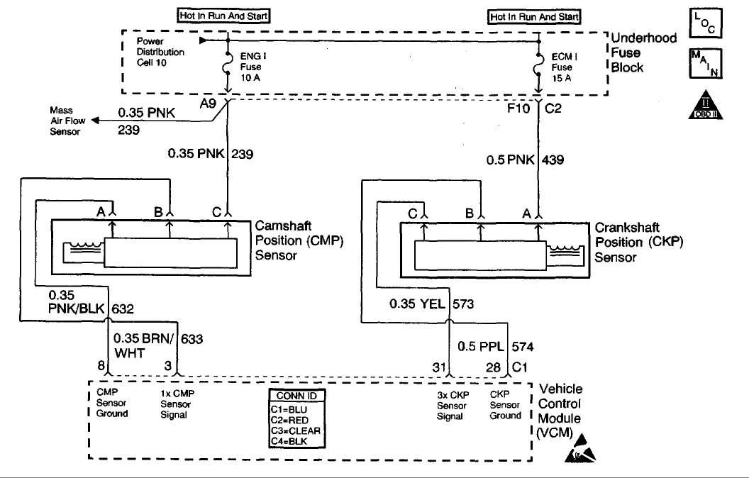
CIRCUIT DESCRIPTION
This Diagnostic Trouble Code (DTC) monitors the Crankshaft Position (CKP) and the Camshaft Position (CMP) signals to determine if they are synchronized. If both signals are not observed by the control module within a narrow time window, the Vehicle Control Module (VCM) will determine that an error has occurred.
CONDITIONS FOR RUNNING THE DTC
The engine is running.
CONDITIONS FOR SETTING THE DTC
When the engine is running, the cam sensor reference pulse is not detected at the correct position relative to the crankshaft position sensor pulse.
ACTION TAKEN WHEN THE DTC SETS
* The control module illuminates the Malfunction Indicator Lamp (MIL) if a failure is detected during 2 consecutive key cycles.
* The control module sets the DTC and records the operating conditions at the time the diagnostic failed. The failure information is stored in the scan tool Freeze Frame and Failure Records.
CONDITIONS FOR CLEARING THE MIL OR DTC
* The control module turns OFF the MIL after 3 consecutive drive trips when the test has run and passed.
* A history DTC will clear if no fault conditions have been detected for 40 warm-up cycles. A warm-up cycle occurs when the coolant temperature has risen 22°C (40°F) from the startup coolant temperature and the engine coolant reaches a temperature that is more than 70°C (158°F) during the same ignition cycle.
* Use a scan tool in order to clear the DTCs.
DIAGNOSTIC AIDS
Check the following items:
A loose CMP sensor causing a variance in the sensor signal.
* Excessive free play in the timing chain and gear assembly.
* Incorrectly installed distributor - 1 tooth off in either advance or retard positions.
* A loose distributor rotor on the distributor shaft.
* A loose or missing distributor hold down bolt.
An intermittent may be caused by any of the following conditions:
* A poor connection
* Rubbed through wire insulation
* A broken wire inside the insulation
Thoroughly inspect any circuitry that is suspected of causing the intermittent complaint. Refer to Testing for intermittent and Poor Connections in Diagrams.
If a repair is necessary, refer to Wiring Repairs or Connector Repairs in Diagrams.
Diagnostic Chart
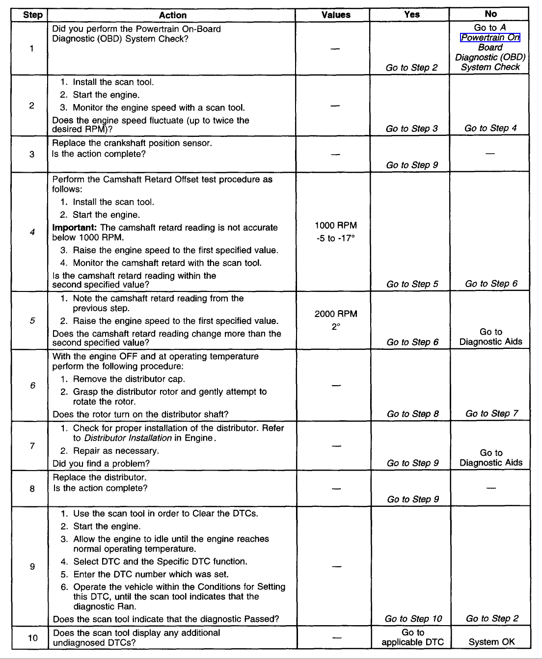
TEST DESCRIPTION
The numbers below refer to the step numbers on the table.
4. This test will determine if this DTC is intermittent.
5. If there is a variance in the camshaft sensor signal it will be detected in this step.
6. Unintentional damage to the distributor shaft may result if excessive pressure is used to rotate the distributor.
Schematic

CIRCUIT DESCRIPTION
This Diagnostic Trouble Code (DTC) monitors the Crankshaft Position (CKP) and the Camshaft Position (CMP) signals to determine if they are synchronized. If both signals are not observed by the control module within a narrow time window, the Vehicle Control Module (VCM) will determine that an error has occurred.
CONDITIONS FOR RUNNING THE DTC
The engine is running.
CONDITIONS FOR SETTING THE DTC
When the engine is running, the cam sensor reference pulse is not detected at the correct position relative to the crankshaft position sensor pulse.
ACTION TAKEN WHEN THE DTC SETS
* The control module illuminates the Malfunction Indicator Lamp (MIL) if a failure is detected during 2 consecutive key cycles.
* The control module sets the DTC and records the operating conditions at the time the diagnostic failed. The failure information is stored in the scan tool Freeze Frame and Failure Records.
CONDITIONS FOR CLEARING THE MIL OR DTC
* The control module turns OFF the MIL after 3 consecutive drive trips when the test has run and passed.
* A history DTC will clear if no fault conditions have been detected for 40 warm-up cycles. A warm-up cycle occurs when the coolant temperature has risen 22°C (40°F) from the startup coolant temperature and the engine coolant reaches a temperature that is more than 70°C (158°F) during the same ignition cycle.
* Use a scan tool in order to clear the DTCs.
DIAGNOSTIC AIDS
Check the following items:
A loose CMP sensor causing a variance in the sensor signal.
* Excessive free play in the timing chain and gear assembly.
* Incorrectly installed distributor - 1 tooth off in either advance or retard positions.
* A loose distributor rotor on the distributor shaft.
* A loose or missing distributor hold down bolt.
An intermittent may be caused by any of the following conditions:
* A poor connection
* Rubbed through wire insulation
* A broken wire inside the insulation
Thoroughly inspect any circuitry that is suspected of causing the intermittent complaint. Refer to Testing for intermittent and Poor Connections in Diagrams.
If a repair is necessary, refer to Wiring Repairs or Connector Repairs in Diagrams.
Diagnostic Chart

TEST DESCRIPTION
The numbers below refer to the step numbers on the table.
4. This test will determine if this DTC is intermittent.
5. If there is a variance in the camshaft sensor signal it will be detected in this step.
6. Unintentional damage to the distributor shaft may result if excessive pressure is used to rotate the distributor.
#7
P1875
Schematic
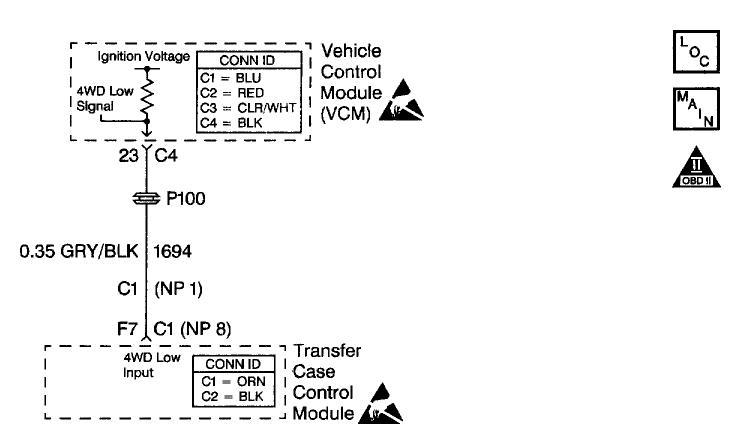
CIRCUIT DESCRIPTION
The four wheel drive (4WD) low circuit consists of the Vehicle Control Module (VCM) , a Transfer Case Control Module (TCCM) and the circuit wiring. The TCCM controls the 4WD low signal on circuit 1694. When the operator selects 4WD low, the TCCM grounds circuit 1694 and the 4WD low signal voltage on the circuit changes from ignition voltage to zero volts . The VCM then compensates for transfer case gear reduction in the transmission Output Shaft Speed (OSS) signal. The VCM uses the transmission OSS signal to adjust shift points, line pressure and Torque Converter Clutch (TCC) scheduling.
When the VCM detects a continuous open or short to ground in the 4WD low circuit, then DTC P1875 sets. DTC P1875 is a type B DTC.
CONDITIONS FOR RUNNING THE DTC
* No TP sensor DTCs P0122, or P0123.
* No VSS assembly DTCs P0502 or P0503.
* No TCC solenoid valve DTC P0740.
* No TCC stuck ON DTC P0742.
* No 1-2 SS valve DTCs P0751 or P0753.
* No 2-3 SS valve DTCs P0756 or P0758.
* No TFP manual valve position switch DTC P1810.
* No TCC PWM solenoid valve DTC P1860.
* The engine speed is greater than 450 RPM for 5 seconds .
* The engine is not in fuel cutoff.
* The gear range is D4.
* The vehicle speed is greater than 11 km/h (7 mph ).
* The TP angle is 17-50% .
* The engine torque is between 50-400 lb ft .
* The engine vacuum is between 0-105 kPa .
* The shift solenoid performance counters are zero.
* The TFT is 20-130°C (68-266°F) .
CONDITIONS FOR SETTING THE DTC
DTC P1875 sets if one of the following conditions occurs:
Condition 1
* The 4WD low switch is in 4WD low.
* The transfer case is not in 4WD low.
* The TCC slip speed is -3000 to -50 RPM .
* The transfer case ratio is 0.8-1.2 (the transfer case ratio is the engine speed divided by the transfer case output speed).
* All conditions are met for 5 seconds .
Condition 2
* The 4WD low switch is not in 4WD low.
* The transfer case is in 4WD low.
* The TCC is commanded ON.
* The TCC slip speed is 100 to 3000 RPM .
* The transfer case ratio is 2.5-2.9.
* All conditions are met for 10 seconds .
ACTION TAKEN WHEN THE DTC SETS
* The VCM illuminates the Malfunction Indicator Lamp (MIL) during the second consecutive trip in which the Conditions for Setting the DTC are met.
* The VCM commands a normal shift pattern (not a 4WD low shift pattern).
* The VCM records the operating conditions when the Conditions for Setting the DTC are met. The VCM stores this information as Freeze Frame and Failure Records.
* The VCM stores DTC P1875 in VCM history during the second consecutive trip in which the Conditions for Setting the DTC are met.
CONDITIONS FOR CLEARING THE MIL/DTC
* The VCM turns OFF the MIL during the third consecutive trip in which the diagnostic test runs and passes.
* A scan tool can clear the MIL/DTC.
* The VCM clears the DTC from VCM history if the vehicle completes 40 warm-up cycles without an emission-related diagnostic fault occurring.
* The VCM cancels the DTC default actions when the fault no longer exists and/or the ignition switch is OFF long enough in
Schematic

CIRCUIT DESCRIPTION
The four wheel drive (4WD) low circuit consists of the Vehicle Control Module (VCM) , a Transfer Case Control Module (TCCM) and the circuit wiring. The TCCM controls the 4WD low signal on circuit 1694. When the operator selects 4WD low, the TCCM grounds circuit 1694 and the 4WD low signal voltage on the circuit changes from ignition voltage to zero volts . The VCM then compensates for transfer case gear reduction in the transmission Output Shaft Speed (OSS) signal. The VCM uses the transmission OSS signal to adjust shift points, line pressure and Torque Converter Clutch (TCC) scheduling.
When the VCM detects a continuous open or short to ground in the 4WD low circuit, then DTC P1875 sets. DTC P1875 is a type B DTC.
CONDITIONS FOR RUNNING THE DTC
* No TP sensor DTCs P0122, or P0123.
* No VSS assembly DTCs P0502 or P0503.
* No TCC solenoid valve DTC P0740.
* No TCC stuck ON DTC P0742.
* No 1-2 SS valve DTCs P0751 or P0753.
* No 2-3 SS valve DTCs P0756 or P0758.
* No TFP manual valve position switch DTC P1810.
* No TCC PWM solenoid valve DTC P1860.
* The engine speed is greater than 450 RPM for 5 seconds .
* The engine is not in fuel cutoff.
* The gear range is D4.
* The vehicle speed is greater than 11 km/h (7 mph ).
* The TP angle is 17-50% .
* The engine torque is between 50-400 lb ft .
* The engine vacuum is between 0-105 kPa .
* The shift solenoid performance counters are zero.
* The TFT is 20-130°C (68-266°F) .
CONDITIONS FOR SETTING THE DTC
DTC P1875 sets if one of the following conditions occurs:
Condition 1
* The 4WD low switch is in 4WD low.
* The transfer case is not in 4WD low.
* The TCC slip speed is -3000 to -50 RPM .
* The transfer case ratio is 0.8-1.2 (the transfer case ratio is the engine speed divided by the transfer case output speed).
* All conditions are met for 5 seconds .
Condition 2
* The 4WD low switch is not in 4WD low.
* The transfer case is in 4WD low.
* The TCC is commanded ON.
* The TCC slip speed is 100 to 3000 RPM .
* The transfer case ratio is 2.5-2.9.
* All conditions are met for 10 seconds .
ACTION TAKEN WHEN THE DTC SETS
* The VCM illuminates the Malfunction Indicator Lamp (MIL) during the second consecutive trip in which the Conditions for Setting the DTC are met.
* The VCM commands a normal shift pattern (not a 4WD low shift pattern).
* The VCM records the operating conditions when the Conditions for Setting the DTC are met. The VCM stores this information as Freeze Frame and Failure Records.
* The VCM stores DTC P1875 in VCM history during the second consecutive trip in which the Conditions for Setting the DTC are met.
CONDITIONS FOR CLEARING THE MIL/DTC
* The VCM turns OFF the MIL during the third consecutive trip in which the diagnostic test runs and passes.
* A scan tool can clear the MIL/DTC.
* The VCM clears the DTC from VCM history if the vehicle completes 40 warm-up cycles without an emission-related diagnostic fault occurring.
* The VCM cancels the DTC default actions when the fault no longer exists and/or the ignition switch is OFF long enough in
#8
P0300
CIRCUIT DESCRIPTION
The Crankshaft Position (CKP) sensor is the primary input to determine if misfire is occurring. Engine misfire is detected by monitoring crankshaft speed variations between cylinders. If a crankshaft deceleration occurs during a combustion or power stroke, the control module will compare this change in crankshaft speed to the previous cylinder. If the crankshaft speed change is more than a maximum allowable speed, the misfire is detected. Misfire may occur in a specific cylinder or in all cylinders randomly.
When an engine is misfiring, brief decelerations in crankshaft rotational speed will be detected by the CKP. The control module determines which cylinder has misfired based upon the Camshaft Position (CMP) sensor input. Misfire data is stored for each cylinder in separate accumulators. After 100 combustion events, the misfire totals are compared to a calibrated maximum number. If the misfire is excessive, this Diagnostic Trouble Code (DTC) will set.
CONDITIONS FOR RUNNING THE DTC
IMPORTANT: If start-up ECT is below -7°C (20°F) , misfire detection is delayed until ECT is more than 21°C (70°F) . If start-up ECT is more than -7°C (20°F) , misfire detection begins after a 5 second delay.
* No active VS sensor DTCs
* No active TP sensor DTCs
* No active MAF sensor DTCs
* No active CKP sensor DTCs
* No active CMP sensor DTCs
* The fuel level is more than 10 percent .
* The engine speed is between 450-5000 RPM .
* The system voltage is between 11-16 volts .
* The throttle position is steady within 2 percent for 100 ms .
CONDITIONS FOR SETTING THE DTC
The VCM detects a deceleration in the crankshaft speed characteristic of either an emission type misfire or a catalyst damaging type misfire.
ACTION TAKEN WHEN THE DTC SETS
If the VCM determines that the engine misfire is significant enough to have a negative impact on emissions, the VCM turns ON the Malfunction Indicator Lamp (MIL) after the misfire has been detected on 2 non-consecutive trips under the same operating conditions. If the misfire is severe enough that catalytic converter damage could result, the MIL flashes while the misfire is present.
CONDITIONS FOR CLEARING THE MIL OR DTC
* The control module turns OFF the MIL after 3 consecutive drive trips when the test has run and passed.
* A history DTC will clear if no fault conditions have been detected for 40 warm-up cycles. A warm-up cycle occurs when the coolant temperature has risen 22°C (40°F) from the startup coolant temperature and the engine coolant reaches a temperature that is more than 70°C (158°F) during the same ignition cycle.
* Use a scan tool in order to clear the DTCs.
DIAGNOSTIC AIDS
The Misfire Index counts the number of misfires. The scan tool can monitor the Misfire Index. There is a current and history misfire counter for each cylinder. Use the current misfire counter in order to determine which cylinder is misfiring or use the history misfire counter for misfires that are not currently present. Many different condition could cause an intermittent misfire.
Check for the following conditions:
* Check the IC control circuit for a intermittent short to ground.
* Check the spark plug wires and the coil wire for the following conditions:
* Ensure that the spark plug wires are securely attached to the spark plugs and the distributor cap.
* Check the wire routing in order to ensure that cross-firing is not occurring.
* If the misfire occurs when the weather is damp, the problem could be due to worn plug wires.
* Check for contaminated fuel or a low fuel level and the following conditions:
* Check the fuel condition and quality. Dirty or contaminated fuel could cause a misfire condition.
* If the fuel level is low, the fuel pump may draw air into the fuel rail, causing a stumble and possible misfire c
#9
P1870
Schematic
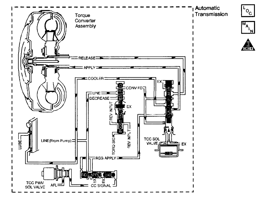
CIRCUIT DESCRIPTION
The Vehicle Control Module (VCM) monitors the difference between engine speed and transmission output speed. In D3 drive range with the TCC engaged, the engine speed should closely match the transmission output speed. In D4 drive range, with the TCC engaged, the TCC slip speed should be -20 to +50 RPM .
When the VCM detects excessive TCC slip when the TCC should be engaged, then DTC P1870 sets. DTC P1870 is a type B DTC.
CONDITIONS FOR RUNNING THE DTC
* No TP sensor DTCs P0122 or P0123.
* No VSS assembly DTCs P0502 or P0503.
* No TFT sensor DTCs P0711, P0712 or P0713.
* No TCC solenoid valve DTC P0740.
* No 1-2 SS valve DTC P0753.
* No 2-3 SS valve DTC P0758.
* No TFP manual valve position switch DTC P1810.
* No TCC PWM solenoid valve DTC P1860.
* The engine speed is greater than 450 RPM for 5 seconds .
* The engine is not in fuel cutoff.
* The engine torque is 50-400 lb ft .
* The engine vacuum is 0-150 kPa .
* The TP angle is 9-35% .
* The vehicle speed is 48-112 km/h (30-70 mph ).
* The engine speed is 1500-3000 RPM .
* The speed ratio is 0.69-0.88 (speed ratio is engine speed divided by the output speed).
* The gear range is D4.
* The commanded gear is not 1st gear.
* The TFT is 20-130°C (68-266°F) .
* The shift solenoid performance diagnostic counters are zero.
CONDITIONS FOR SETTING THE DTC
DTC P1870 sets if the following conditions occur for three TCC cycles.
* The TCC is commanded ON for 5 seconds .
* The TCC is at maximum duty cycle (95% ) for 5 seconds .
* The TCC slip speed is 130-800 RPM for 7 seconds .
ACTION TAKEN WHEN THE DTC SETS
* The VCM illuminates the Malfunction Indicator Lamp (MIL) during the second consecutive trip in which the Conditions for Setting the DTC are met.
* The VCM commands maximum line pressure. The VCM inhibits TCC engagement. The VCM inhibits 4th gear if the transmission is in hot mode.
* The VCM freezes shift adapts from being updated.
* The VCM records the operating conditions when the Conditions for Setting the DTC are met. The VCM stores this information as Freeze Frame and Failure Records.
* The VCM stores DTC P1870 in VCM history during the second consecutive trip in which the Conditions for Setting the DTC are met.
CONDITIONS FOR CLEARING THE MIL/DTC
* The VCM turns OFF the MIL during the third consecutive trip in which the diagnostic test runs and passes.
* A scan tool can clear the MIL/DTC.
* The VCM clears the DTC from VCM history if the vehicle completes 40 warm-up cycles without an emission-related diagnostic fault occurring.
* The VCM cancels the DTC default actions when the fault no longer exists and/or the ignition switch is OFF long enough in order to power down the VCM.
DIAGNOSTIC AIDS
* Bronze material found in the transmission oil pan may indicate stator shaft bushing wear. If bushing wear is suspected, inspect the stator shaft and the input (turbine) shaft for damage.
* Refer to Symptom Diagnosis for more information.
Diagnostic Chart (Part 1 Of 4)
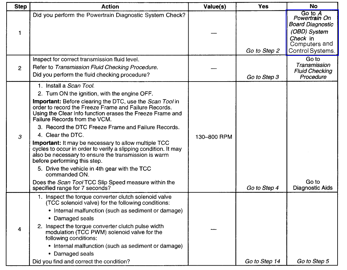
Diagnostic Chart (Part 2 Of 4)
[URL=http://i11.photobucket.com/albums/a187/swartlkk/2000%20Bravada/P1870_DC2of4.gif][IMG]http://
Schematic

CIRCUIT DESCRIPTION
The Vehicle Control Module (VCM) monitors the difference between engine speed and transmission output speed. In D3 drive range with the TCC engaged, the engine speed should closely match the transmission output speed. In D4 drive range, with the TCC engaged, the TCC slip speed should be -20 to +50 RPM .
When the VCM detects excessive TCC slip when the TCC should be engaged, then DTC P1870 sets. DTC P1870 is a type B DTC.
CONDITIONS FOR RUNNING THE DTC
* No TP sensor DTCs P0122 or P0123.
* No VSS assembly DTCs P0502 or P0503.
* No TFT sensor DTCs P0711, P0712 or P0713.
* No TCC solenoid valve DTC P0740.
* No 1-2 SS valve DTC P0753.
* No 2-3 SS valve DTC P0758.
* No TFP manual valve position switch DTC P1810.
* No TCC PWM solenoid valve DTC P1860.
* The engine speed is greater than 450 RPM for 5 seconds .
* The engine is not in fuel cutoff.
* The engine torque is 50-400 lb ft .
* The engine vacuum is 0-150 kPa .
* The TP angle is 9-35% .
* The vehicle speed is 48-112 km/h (30-70 mph ).
* The engine speed is 1500-3000 RPM .
* The speed ratio is 0.69-0.88 (speed ratio is engine speed divided by the output speed).
* The gear range is D4.
* The commanded gear is not 1st gear.
* The TFT is 20-130°C (68-266°F) .
* The shift solenoid performance diagnostic counters are zero.
CONDITIONS FOR SETTING THE DTC
DTC P1870 sets if the following conditions occur for three TCC cycles.
* The TCC is commanded ON for 5 seconds .
* The TCC is at maximum duty cycle (95% ) for 5 seconds .
* The TCC slip speed is 130-800 RPM for 7 seconds .
ACTION TAKEN WHEN THE DTC SETS
* The VCM illuminates the Malfunction Indicator Lamp (MIL) during the second consecutive trip in which the Conditions for Setting the DTC are met.
* The VCM commands maximum line pressure. The VCM inhibits TCC engagement. The VCM inhibits 4th gear if the transmission is in hot mode.
* The VCM freezes shift adapts from being updated.
* The VCM records the operating conditions when the Conditions for Setting the DTC are met. The VCM stores this information as Freeze Frame and Failure Records.
* The VCM stores DTC P1870 in VCM history during the second consecutive trip in which the Conditions for Setting the DTC are met.
CONDITIONS FOR CLEARING THE MIL/DTC
* The VCM turns OFF the MIL during the third consecutive trip in which the diagnostic test runs and passes.
* A scan tool can clear the MIL/DTC.
* The VCM clears the DTC from VCM history if the vehicle completes 40 warm-up cycles without an emission-related diagnostic fault occurring.
* The VCM cancels the DTC default actions when the fault no longer exists and/or the ignition switch is OFF long enough in order to power down the VCM.
DIAGNOSTIC AIDS
* Bronze material found in the transmission oil pan may indicate stator shaft bushing wear. If bushing wear is suspected, inspect the stator shaft and the input (turbine) shaft for damage.
* Refer to Symptom Diagnosis for more information.
Diagnostic Chart (Part 1 Of 4)

Diagnostic Chart (Part 2 Of 4)
[URL=http://i11.photobucket.com/albums/a187/swartlkk/2000%20Bravada/P1870_DC2of4.gif][IMG]http://
#10
P0440
Schematic
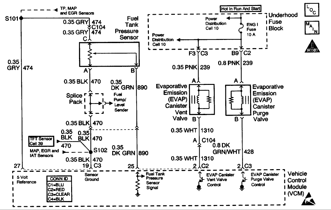
CIRCUIT DESCRIPTION
The evaporative system includes the following components:
* The fuel tank
* The EVAP vent solenoid
* The fuel tank pressure sensor
* The fuel pipes and hoses The vapor lines
* The fuel cap
* The evaporative emission canister
* The purge lines
* The EVAP purge solenoid
The evaporative leak detection diagnostic strategy is based on applying a vacuum to the EVAP system and monitoring the vacuum decay rate. The Vehicle Control Module (VCM) monitors the vacuum level via the fuel tank pressure sensor input. At an appropriate time, the EVAP purge solenoid and the EVAP vent solenoid turn ON, allowing the engine vacuum to draw a small vacuum on the entire evaporative emission system. If a sufficient vacuum level cannot be achieved, a large leak or an EVAP system malfunction is indicated. The following conditions can cause this problem:
* A disconnected or malfunctioning fuel tank pressure sensor
* A missing, malfunctioning, improperly installed, or loose fuel cap
* A disconnected, damaged, pinched, or blocked EVAP purge line
* A disconnected or damaged EVAP vent hose
* A disconnected, damaged, pinched, or blocked fuel tank vapor line
* A disconnected or malfunctioning EVAP purge solenoid
* A disconnected or malfunctioning EVAP vent solenoid
* An open ignition feed circuit to the EVAP vent or purge solenoid
* A damaged EVAP canister
* A leaking fuel sender assembly O-ring
* A leaking fuel tank or fuel filler neck
Any of the above conditions can set a DTC P0440.
CONDITIONS FOR RUNNING THE DTC
* No active MAP sensor DTCs
* No active TP sensor DTCs
* No active VS sensor DTCs
* No active O2 sensor DTCs
* No active ECT sensor DTCs
* No active IAT sensor DTCs
* DTC P0125 not active
* The system voltage is between 10-17 volts
* The fuel level is between 12.5-87 percent .
* The ECT is between 4°C-30°C (39°F-86°F)
* The IAT is between 4°C-30°C (39°F-86°F)
* The cold start temperature difference (ECT minus IAT) is less than 1.5°C when the IAT is more than the ECT or 8°C when the ECT is more than the IAT
* The BARO is more than 73 kPa
CONDITIONS FOR SETTING THE DTC
The EVAP system is unable to generate a vacuum more than a calibrated value over a specified period of time.
ACTION TAKEN WHEN THE DTC SETS
* This is a type A DTC that behaves like a B type, in which the VCM illuminates the MIL after the second key cycle.
* The VCM stores the conditions that were present when the DTC sets as a Freeze Frame/Failure Records data.
CONDITIONS FOR CLEARING THE MIL OR DTC
* The control module turns OFF the MIL after 3 consecutive drive trips when the test has run and passed.
* A history DTC will clear if no fault conditions have been detected for 40 warm-up cycles. A warm-up cycle occurs when the coolant temperature has risen 22°C (40°F) from the startup coolant temperature and the engine coolant reaches a temperature that is more than 70°C (158°F) during the same ignition cycle.
* Use a scan tool in order to clear the DTCs.
DIAGNOSTIC AIDS
IMPORTANT: An accurate indication of fuel level is required for the VCM to properly pass or fail this DTC. Always diagnose fuel level sensor DTCs before pe
Schematic

CIRCUIT DESCRIPTION
The evaporative system includes the following components:
* The fuel tank
* The EVAP vent solenoid
* The fuel tank pressure sensor
* The fuel pipes and hoses The vapor lines
* The fuel cap
* The evaporative emission canister
* The purge lines
* The EVAP purge solenoid
The evaporative leak detection diagnostic strategy is based on applying a vacuum to the EVAP system and monitoring the vacuum decay rate. The Vehicle Control Module (VCM) monitors the vacuum level via the fuel tank pressure sensor input. At an appropriate time, the EVAP purge solenoid and the EVAP vent solenoid turn ON, allowing the engine vacuum to draw a small vacuum on the entire evaporative emission system. If a sufficient vacuum level cannot be achieved, a large leak or an EVAP system malfunction is indicated. The following conditions can cause this problem:
* A disconnected or malfunctioning fuel tank pressure sensor
* A missing, malfunctioning, improperly installed, or loose fuel cap
* A disconnected, damaged, pinched, or blocked EVAP purge line
* A disconnected or damaged EVAP vent hose
* A disconnected, damaged, pinched, or blocked fuel tank vapor line
* A disconnected or malfunctioning EVAP purge solenoid
* A disconnected or malfunctioning EVAP vent solenoid
* An open ignition feed circuit to the EVAP vent or purge solenoid
* A damaged EVAP canister
* A leaking fuel sender assembly O-ring
* A leaking fuel tank or fuel filler neck
Any of the above conditions can set a DTC P0440.
CONDITIONS FOR RUNNING THE DTC
* No active MAP sensor DTCs
* No active TP sensor DTCs
* No active VS sensor DTCs
* No active O2 sensor DTCs
* No active ECT sensor DTCs
* No active IAT sensor DTCs
* DTC P0125 not active
* The system voltage is between 10-17 volts
* The fuel level is between 12.5-87 percent .
* The ECT is between 4°C-30°C (39°F-86°F)
* The IAT is between 4°C-30°C (39°F-86°F)
* The cold start temperature difference (ECT minus IAT) is less than 1.5°C when the IAT is more than the ECT or 8°C when the ECT is more than the IAT
* The BARO is more than 73 kPa
CONDITIONS FOR SETTING THE DTC
The EVAP system is unable to generate a vacuum more than a calibrated value over a specified period of time.
ACTION TAKEN WHEN THE DTC SETS
* This is a type A DTC that behaves like a B type, in which the VCM illuminates the MIL after the second key cycle.
* The VCM stores the conditions that were present when the DTC sets as a Freeze Frame/Failure Records data.
CONDITIONS FOR CLEARING THE MIL OR DTC
* The control module turns OFF the MIL after 3 consecutive drive trips when the test has run and passed.
* A history DTC will clear if no fault conditions have been detected for 40 warm-up cycles. A warm-up cycle occurs when the coolant temperature has risen 22°C (40°F) from the startup coolant temperature and the engine coolant reaches a temperature that is more than 70°C (158°F) during the same ignition cycle.
* Use a scan tool in order to clear the DTCs.
DIAGNOSTIC AIDS
IMPORTANT: An accurate indication of fuel level is required for the VCM to properly pass or fail this DTC. Always diagnose fuel level sensor DTCs before pe


